Till now we were using a serial monitor to print the messages from Arduino. But now, we will use a 16×2 character LCD to print the messages. Here 16×2 means we can print 2 lines of 16 characters long. In this project, we will look at how we can interface a 16×2 LCD with Arduino and print some characters on it.
Table of Contents
Introduction to 16×2 LCD
As said before a 16×2 LCD can display 2 lines of 16 characters long messages. It prints characters in matrix form. It prints a character with the help of a 5×7 dot matrix. You can see this in the image below.
This is a graphical image of a 16×2 LCD. You can say that it used a 5×7 pixel font. Here is an example of a 5×7 pixel character.
The figure above shows how we can write ‘A’ using a 5×7 dot matrix. This dot matrix is implemented 16 times in 2 rows are a total of 32 dot matrices. So we can write small letters, capital letters, numbers, and custom designs by making patterns on the dot matrices.
Pin diagram of the 16×2 LCD
Look at the pin diagram of the 16×2 LCD.
Now let’s understand the pin description and what is its function. Vss and Vdd are the power pins. You can power the LCD using 5V. VE is the contrast voltage pin. Using this pin you can set the contrast of the LCD by adjusting the voltage on this pin. We can adjust the voltage on the pin with a potentiometer.
RS is the register select pin. Using this pin we can set the data on data pins as a command (instruction) or character data which has to print. Print on a new line set cursor position, blinking cursor are some examples of the LCD instruction. When this pin is low then it will select the command register and when it is high then it will select the character register.
RW is the read/write pin of the LCD. When it is high then it will make its data available to read for other (host) microcontrollers. You can simply say that it outputs the character data. When the RW pin is low then it will take the input from other devices.
E is the enable pin. To give the LCD any command or character data we need to give this pin a high going trigger pulse.
D0-D8 is the data pins through which LCD transfers the data. LED+ and LED- are the backlight LED pins. If you want a backlight from the LCD then supply 5 volts through on those pins.
LCD working
LCD has separate processing and memory units. It can execute pre-coded instructions as said earlier. To print any character on LCD you’ll need to give ASCII value to it. If you want to print ‘A’ on the LCD then you will need to give 65 (ASCII value of capital A) to the LCD. If you will convert 65 in binary then you will get 01000001. In LCD LSB data pin is D0 and MSB pin is D7. So you have to set the pins according to the binary number you’ve got. To understand the working of an LCD, you must see this video.
By watching this video you can understand the initialization and data flow of the 16×2 LCD. First, we need to initialize the LCD according to your hardware connection (4-bit or 8-bit). Then you can instruct the LCD as your wish. To give LCD an instruction you need to keep the RS pin low and to give it character data you need to keep RS high. Data entry in LCD happens on every high pulse on enable (E) pin.
Some important LCD instructions
Here are some important LCD instructions.
| Command | Hex code |
|---|---|
| LCD ON, cursor ON | 0F |
| Clear display screen | 01 |
| Return home | 02 |
| Decrement cursor (shift cursor to left) | 04 |
| Increment cursor (shift cursor to right) | 06 |
| Shift display right | 05 |
| Shift display left | 07 |
| Display ON, cursor blinking | 0E |
| Force cursor to the beginning of the first line | 80 |
| Force cursor to the beginning of the second line | C0 |
| 2 lines and 5×7 matrix | 38 |
| Cursor line 1 position 3 | 83 |
| Activate the second line | 3C |
| Display OFF, cursor OFF | 08 |
| Jump to the second line, position 1 | C1 |
| Display ON, cursor OFF | 0C |
| Jump to the second line, position 2 | C2 |
16×2 LCD connection with Arduino
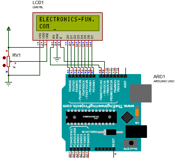
Now you will see how you can connect 16×2 LCD with Arduino and start printing something on it. So look at the circuit diagram given below.
You can see that data pins of LCD (D0-D7) are connected to digital pins 0-7 of Arduino which is port D of the ATMEGA328P microcontroller. I will use port manipulation to give data to LCD since it is easy to use. You will notice that in the Arduino program. RS pin is connected to pin 8 and E (enable) pin is connected to pin 9 of Arduino. Now we can control all data flow to LCD using Arduino. Now, look at the Arduino program to print something on the LCD.
Arduino code for the LCD
int RS = 8;                         //register select pin
int E = 9;                          //Enable pin
char message[] = "ELECTRONICS-FUN.COM"; //Message you want to print
void setup()
{
  DDRD = B11111111;                 // set PORT D (Arduino digital 7~0) to outputs for D0-D7 of LCD
  pinMode(RS, OUTPUT);
  pinMode(E, OUTPUT);

  LCD_init();                       //LCD initialization
  int NumofChar = sizeof(message);  //finding the number of character in message

  for (int i = 0; i < NumofChar; i++) {
    if (i == 16) {                  //Checking if message is having any 17th character
      LCD_cmd(0xC0);                //Force cursor to begining of 2nd line
    }
    Print(message[i]);              //Printing each character of message one by one
  }
}

void loop()
{

}

void LCD_cmd(int command) {         //Method to give the commands to LCD
  digitalWrite(RS, LOW);
  digitalWrite(E, LOW);
  PORTD = command;                  //PORT pins will be high or low according to binary value of command
  digitalWrite(E, HIGH);
  delay(5);
  digitalWrite(E, LOW);
}

void LCD_init() {
  LCD_cmd(0x38);                    //LCD command to set it in 8-bit mode
  LCD_cmd(0x0F);                    //Command for LCD to on the LCD and cursor
}

void Print(char a) {                //method to print a character on LCD
  digitalWrite(RS, HIGH);
  digitalWrite(E, LOW);
  PORTD = int(a);                   //convert char data to int (ASCII)
  digitalWrite(E, HIGH);
  delay(5);
  digitalWrite(E, LOW);
}
Every part of the code has comments to explain its functionality, but still, I will give a summary of the code. First of all, I have taken 3 variables, one for the RS (register select) pin, second for the E (enable) pin, and third for the message that you want to print on LCD. In the setup section, I have declared the pins 0 to 7 of Arduino as output using DDRD instruction. I gave B11111111 to the DDRD instruction so it set all 8 pins as output. If I had given any 0 in binary number then DDRD would have set the equivalent pin as an input. So this way I avoided using the pinMode function repeatedly.
Then I have declared enable and register select pins as output using the pinMode function. After that, I have called a function named LCD_init(). This function has the commands for LCD to initialize it. LCD_init() function uses LCD_cmd() function to give the instruction data to the LCD. LCD_cmd() function contains all methods to give the LCD instruction such as keep register select pin low and give trigger pulse to enable pin.
Then I counted the number of characters in a message using the sezeof() function to iterate to each character in the message and print it. I have implanted a logic in for loop to check if any 17th character exits. If yes then I have LCD will get the command to print it on the next line. That’s all.
16×2 LCD with Arduino using library
In the Arduino programming language, there are some libraries for the LCD. That makes our code easier and more understandable. Let’s see a code with the help of the Arduino library for LCD.
/*

 This sketch prints "Hello World!" to the LCD
 and shows the time.

  The circuit:
 * LCD RS pin to digital pin 8
 * LCD Enable pin to digital pin 9
 * LCD D0 pin to digital pin 0
 * LCD D1 pin to digital pin 1
 * LCD D2 pin to digital pin 2
 * LCD D3 pin to digital pin 3
 * LCD D4 pin to digital pin 4
 * LCD D5 pin to digital pin 5
 * LCD D6 pin to digital pin 6
 * LCD D7 pin to digital pin 7
 * LCD R/W pin to ground
 * LCD VSS pin to ground
 * LCD VCC pin to 5V
 * 10K potentiometer:
 * ends to +5V and ground
 * wiper to LCD VEE pin (pin 3)


*/

// include the library code:
#include

// Arduino and LCD connection
const int rs = 8, en = 9, d0 = 0, d1 = 1, d2 = 2, d3 = 3, d4 = 4, d5 = 5, d6 = 6, d7 = 7;
LiquidCrystal lcd(rs, en, d0, d1, d2, d3, d4, d5, d6, d7);

void setup() {
  // set up the LCD's number of columns and rows:
  lcd.begin(16, 2);
  // Print a message to the LCD.
  lcd.print("hello, world!");
}

void loop() {
  // set the cursor to column 0, line 1
  // (note: line 1 is the second row, since counting begins with 0):
  lcd.setCursor(0, 1);
  // print the number of seconds since reset:
  lcd.print(millis() / 1000);
}
So, this is the code using a library code for the LCD. The code is so simple that you can understand the code by reading the comment. You can try a lot of variations in the code. Go to the Arduino reference page and see the documentation for the LiquidCrystal library. Now look at the output of this code.
Conclusion
You have learned how an LCD works. First of all, you have learned how a character LCD prints something on it. Then you have seen how you can print on LCD without a microcontroller but with the help of manual switches. You have then connected the LCD with Arduino and controlled it with Arduino with and without the help of a library code for LCD.
I have read so many posts about the blogger lovers however this post is really a good piece of writing, keep it up
I have read so many posts about the blogger lovers howeverthis post is really a good piece of writing, keep it up.
whoah this blog is wonderful i really like reading your articles. Keep up the great paintings! You realize, a lot of people are hunting round for this info, you could help them greatly.
whoah this blog is wonderful i really like reading your articles. Keep up the great paintings! You realize, a lot of people are hunting round for this info, you could help them greatly.
whoah this blog is wonderful i really like reading your articles. Keep up the great paintings! You realize, a lot of people are hunting round for this info, you could help them greatly.
I really enjoy reading and also appreciate your work.
I think about it is most required for making more on this get engaged