Today seven segment displays are widely used in almost all electronic circuits. It can display number from 0 to 9 and some characters. In this display 7 segments of LED (light emitting diode) is arranged such as it can display these information. Each segment is denoted by small alphabetical letters. One terminal of all those LED is common, so it can be of two types, common anode and common cathode.
Arrangement of segments and both types of displays are mentioned in figure below.
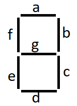
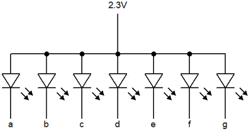
This is a common anode 7-segment display. In this display anode of all LED is common and it is connected to positive voltage. Cathode of all LED is responsible to display numbers or some alphabet. we give 0 volt to a particular cathode according to what we want to display.
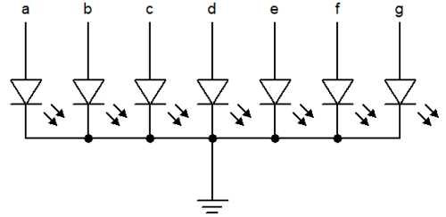
This is a common cathode 7-segment display. In this display cathode of all LED is common and it is connected to zero voltage. Anfode of all LED is responsible to display numbers or some alphabet. we give positive voltage to a particular Anode according to what we want to display.
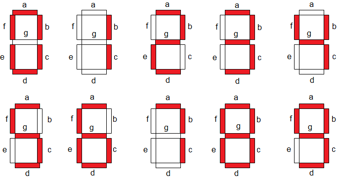
Now, if we have to display 0 on the display then we will keep the ‘g’ segment off and other segment on. We want to design a circuit which will take four binary inputs and print hexadecimal number equivalent to that binary number. You can call this circuit seven segment hex decoder. There are 16 digits in hexadecimal number which are 0-9 numbers and A-F alphabets. We will use common cathode display. See this table.
Links to buy 7-segment displays
| Amazon link for India | Amazon link for other countries |
Table of Contents
7-segment HEX decoder truth table
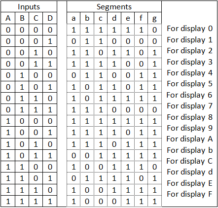
7-segment HEX decoder circuit will turn on and off the segment for displaying a particular information. Here in this table ‘1’means positive voltage and ‘0’ means 0 volt. We are using a common cathode 7-segment display so ‘1’ means a particular segment is on and ‘0’ means a particular segment is off.
We can design the whole circuit by creating Boolean expression and circuit diagram one by one for each segment.
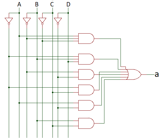
1. For segment ‘a’
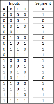
Equation for this table is, a(A,B,C,D) = Σ(0,2,3,5,6,7,8,9,10,12,14,15)
K-map for this equation –
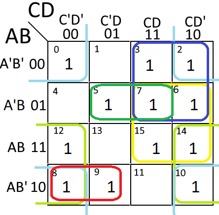
Boolean expression for segment a= AB’C’ + A’BD + AD’ + A’C + BC + B’D’.
Circuit diagram for segment a –
2. For segment ‘b’
Equation for segment b is, b(A,B,C,D) = Σ(0,1,2,3,4,7,8,9,10,13)
K-map for this expression –
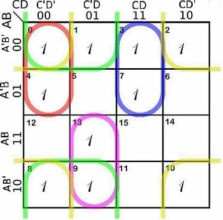
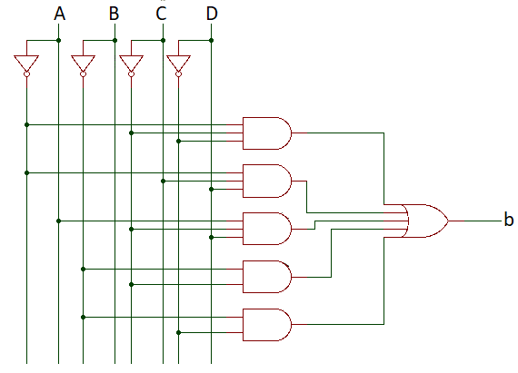
Boolean expression, b = A’C’D’ + A’CD + AC’D + B’C’ + B’D’
Logic diagram –
3. For segment ‘c’
Equation for segment c is, c(A,B,C,D) = Σ(0,1,3,4,5,6,7,8,9,10,11,13)
K-map for this expression –
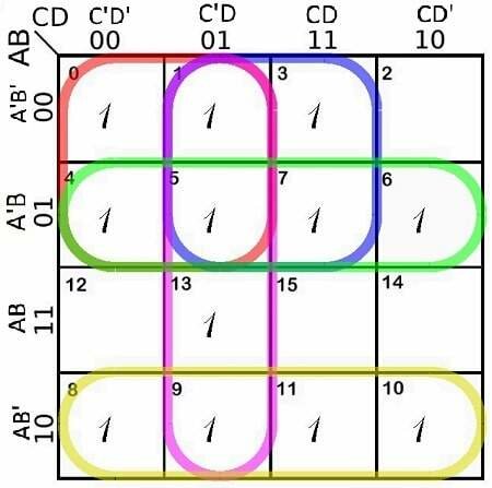
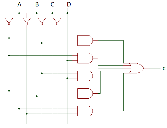
Boolean expression, c = A’C’ + A’D + C’D + A’B + AB’
Logic diagram –
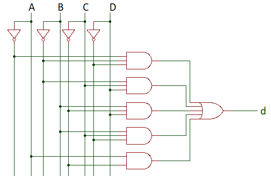
4. For segment ‘d’
Equation for segment d is, d(A,B,C,D) = Σ(0,2,3,5,6,8,9,11,12,13,14)
K-map for this expression –
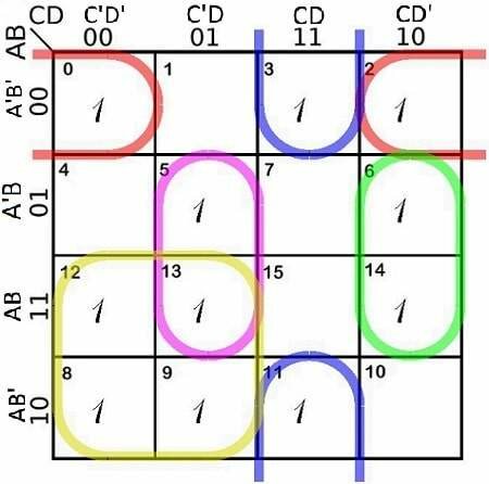
Boolean expression, d = A’B’D’ + B’CD + BC’D + BCD’ + AC’
Logic diagram –
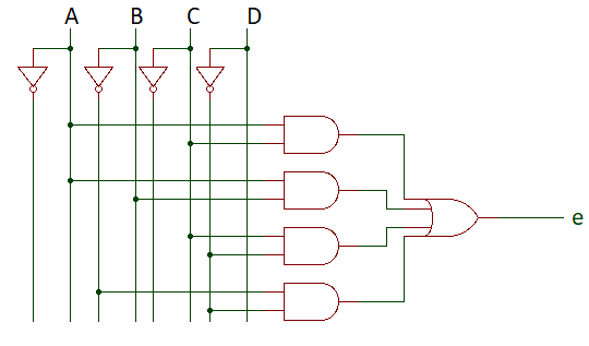
5. For segment ‘e’
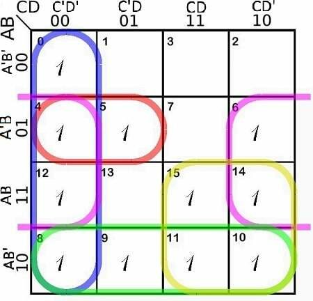
Equation for segment e is, e(A,B,C,D) = Σ(0,2,6,8,10,11,12,13,14,15)
K-map for this expression –
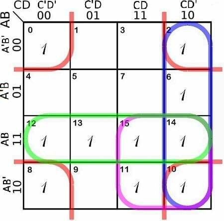
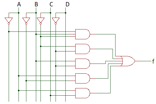
Boolean expression, e = B’D’ + CD’ + AC + AB
Logic diagram –
6. For segment ‘f’
Equation for segment f is, f(A,B,C,D) = Σ(0,4,5,6,8,9,10,11,12,14,15)
K-map for this expression –
Boolean expression, f = A’BC’ + C’D’ + BD’ + AB’ + AC
Logic diagram –
7. For segment ‘g’
Equation for segment g is, g(A,B,C,D) = Σ(2,3,4,5,6,8,9,10,11,13,14,15)
K-map for this expression –
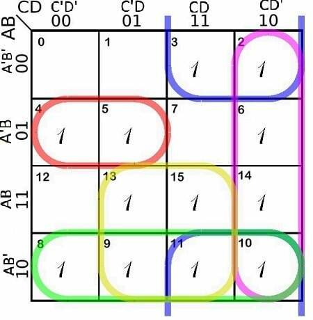
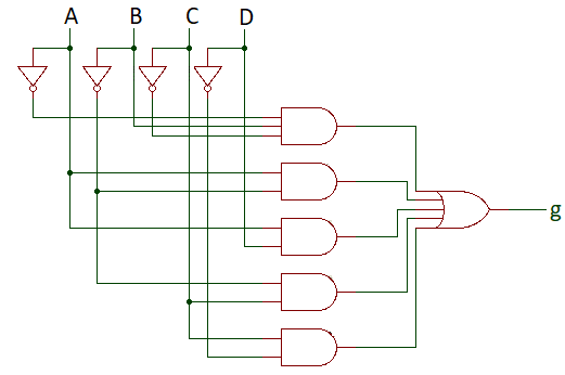
Boolean expression, g = A’BC’ + B’C + CD’ + AB’ + AD
Logic diagram –
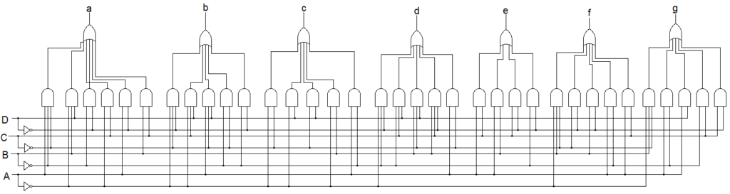
After combining circuits of all segments we will get complete 7-segment HEX decoder circuit.
7 segment hex decoder IC
There are many 7 segment hex decoder ICs are available in the market which works as same as we have build using logic gates. Building the entire 7 segment hex decoder circuit using only logic gates is OK when you want to learn about digital electronics. But when you want to work around a serious 7 segment project or a project where you need to display decimal numbers of equivalent binary number then you need to have these ICs.
These ICs gives us even more features than our logic gate circuit. So first of all we will see the list of ICs we have in the market. Then we will deeply understand an IC which is most popular and available every where. Lastly we will build a circuit using this IC.
- 74LS49 – This IC is from Hitachi Semiconductor and features open collector output.
- 74LS47 – From Hitachi Semiconductor and features 15V output (Common Anode, 74LS48 for common cathode)
- 54C48 – From National Semiconductor
- MC14558B – From Motorola (freescale semiconductor)
- HCF4056B_02 – From STMicroelectronics
- 74C48 – From Fairchild Semiconductor
- CMOS CD4511BF – From Texas Instruments
NOTE – There are many more ICs. You will get more information in datasheet of these ICs.
So these are the ICs are available in the market. Now we will see an IC deeply and design a circuit using it. Most of the IC may be designed for only common cathode or only common anode.
74LS48 BCD to 7 segment decoder
74LS48 is a BCD to 7 segment decoder which is popular and available everywhere which is manufactured by Hitachi Semiconductor and Texas Instruments. It is a 16 pin IC which comes in both DIP (dual in line) and SMD (surface mount device) versions. It has internal pullup resistors so we need less external resistor. Let’s see the pin diagram of 74LS48.
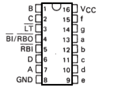
Here A,B,C and D are the binary input and a-g are output for seven segment display. Pin 16 is positive power supply and pin 8 is ground. RBI and RBO is automatic leading and/or trailing-edge zero-blanking control. LT is lamp test which can be performed at any time when BI/RBO is at high level.
Now Let’s see the logic diagram of the 74LS48.
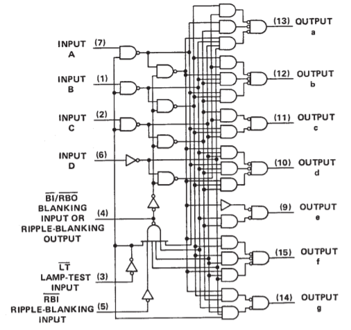
This is almost similar to the circuit that we had build. Extra logic are for control purpose. Now let’s see ho we can connect it to 7 segment display.
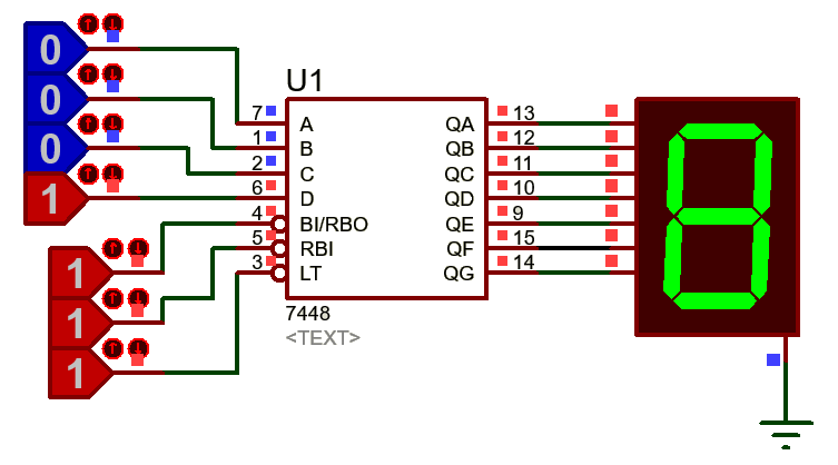
This is the complete circuit to connect a 7 segment decoder IC to 7 segment display. As you can see that we have given the input at A-D input pins and connected the display to a-g pins. We have given the input 1000 and display is showing 8. That means we have sucessfully created the circuit.
74LS47 buying links
This Ic is also a hex to 7-segment decoder but for common anode 7- segment display.
| Amazon link for India | Amazon link for other countries |
Could I ask why to display no 4 the b part is not working instead it shows when try to display no 5
Unfortunately all of the ic’s seem to support only 0-9 digits. Many of them return just blank when the input is at range 10-15. Some of them have really wierd outputs on those inputs. If anyone knows proper hex 7-segment decoder ic, please tell. One way to have compact hex decoding is to use eeprom and write in that the truth table of the decoder.
Yes, all the ic’s support only 0-9 digits. But if you want more digits, you can cascade more than one ic’s. As you have suggested the eeprom decoder is also a very good idea to have a 7-segment decoder.
Except that there are NO Eproms that have just 4 address bits. You would need to build it to decode both hex and ASCII for a dot matrix display.
There is actually a Hex-to-7 Segment Decoder/Driver chip: The MC14495. However, it is quite expensive, if buying new from a reputable source. On the other hand, if you’re willing to gamble a bit, you can find them for a dollar or two on ebay.
Another option is to use the Karnaugh maps provided above and program a PAL/GAL 16V8 rather than the EEPROM (which is also a good choice, but with similar limitations). The output definitions have been neatly described in this article–it’s just a matter of converting them to the programming data for the chip. The disadvantage here is that PAL/GAL output drive is more limited than a dedicated driver chip–around 10mA, which is enough for small LEDs but may not be able to work as well with larger ones that prefer 20mA+ drive currents.
Finally, the cadillac of driver chips is the ICM7212. It’s probably overkill for what you want to do, but it’s an option, especially if you need 4 (or multiples of 4) digit displays.
There is an error in segment B, the correct boolean expression should be
(A’C’D’) + A’CD + AC’D + (A’B’) + B’D’
other than that, it works wonder, thanks
I’m really sorry for that, but now I saw and fixed it. . I think that your suggested expression is also wrong. The expression should be (A’C’D’) + A’CD + AC’D + (B’C’) + B’D’. Thank you TAN AL YEE to inform and suggest me.
Bro what an absolutely amazing web page so well layed out good looking and very informtative I am genuinely impressed
this information will be helpful for making redstone 7 seg. display in minecraft
Can it count up down
No dear! it can’t count but you can add an Up/Down counter for that.
Hi, Does anyone knows how to do this?
Design a combinational circuit that will use and display binary number equivalent to hexadecimal using seven segment common anode with sum of products procedure.
2, truth table
3. k-map– equation
4, circuit diagram ( logic gates)
5, no. of IC specify the IC
I’m not sure what is being asked here. If you are being provided a hex number via a circuit, it’s ALREADY in binary. All you have to do is display either a zero or one for each bit–one per digit.
If you’re using a common cathode display, your logic gate will simply be an inverter for each digit. Your circuit is the b and c segments always on, and the a,d,e,f segments tied to the output of the inverter. When the bit is zero, the inverter will flip and turn your segments on.
If you’re using a common anode display, it’s similar, except you would use a non-inverting buffer to drive the a,d,e,f segments instead of an inverter/inverting buffer.
No k-map required, truth table and circuit diagrams are quite simple.
One two three four five six seven eight nine ten
ROCK AROUND THE CLOCK