We have some advance I/O function in Arduino which allows us to interface some external devices like shift registers, buzzer or some other sensors. Let’s see what those are.
- tone()
- noTone()
- pulseIn()
- pulseInLong()
- shiftin()
- shiftOut()
So these are the function that we have in the advanced I/O category.
Table of Contents
tone()
Tone function generates square wave of a specified frequency (of 50% duty cycle) on any PWM pin. You can specify tone duration if you want. If you haven’t define any duration then it will generate the wave until you don’t call noTone().
You can generate one tone at a time. If you have already defined a tone on any pin then the next tone call will have no affect even after pin is different. If pin is same then it will update the frequency only.
Syntax of tone()
Syntax of tone function in Arduino looks like this.
tone(pin, frequency)
tone(pin, frequency, duration)
Let’s see an example
void setup() {         // put your setup code here, to run once:
  pinMode(3,OUTPUT);
  tone(3,500);
}
void loop() {
  // put your main code here, to run repeatedly:
}
Output:
As you can see that Arduino is generating 500HZ tone at pin 3. We can’t generate tone below than 31HZ frequency. You can set the duration of tone in the third parameter of tone function. Time should be in millisecond.
noTone()
noTone function just stops the square wave that was generating because of tone function. Its syntax looks like this.
noTone(pin)
Let’s stop the tone we have generated in previous code.
void setup() {               // put your setup code here, to run once:
  pinMode(3,OUTPUT);
  tone(3,500);
  delay(6);
  noTone(3);
}
void loop() {
  // put your main code here, to run repeatedly:
}
Output:
This time we have got only three pulses that represents the 6mS time. Because after six millisecond we have called noTone function that stopped the tone. We can get this three voltage pulses using tone function itself. We have to just provide pulse duration of 6mS n tone function like this- tone(3, 500, 6).
pulseIn()
pulseIn function reads a pulse on a pin. The pulse should be either high or low. If we have set the pulesIn function to take a high pulse then it will wait until a low to high pulse transition on that pin. It will start timing when low to high pulse occurs and wait for pulse to go low. As pulse goes low, it stops timer and returns the length of pulse in microseconds. It will return 0 if no pulse occurs within the timeout range, if you have set any. Pulse should be from 10 microseconds to 3 minutes in length. This function may give wrong value for longer pulses.
Let’s see the syntax of pulseIn function.
pulseIn(pin, value)
pusleIn(pin, value, timeout)
Value should be HIGH or LOW. Timeout is the time within pulse starts and it should be in miliseconds.
unsigned long pulseTime;
void setup() {                  // put your setup code here, to run once:
  Serial.begin(9600);
}
void loop() {
  // put your main code here, to run repeatedly:
  pinMode(3,INPUT);
  pulseTime= pulseIn(3, HIGH);
  Serial.println(pulseTime);
}
Output:
pulseInLong()
pulseInLong is an alternative to pulseIn function. It is better at handing long pulses and affected scenario. It works as same as pulseIn function but it can handles long pulse where pulseIn function may give us wrong value. Whereas pulseInLong function may give wrong value for short pulses.
Syntax of pusleInLong is also same as pulseIn function.
pusleInLong(pin, value)
pulseInLong(pin, value, timeout)
shiftIn()
shiftIn function shifts one byte of data one bit at a time in arduino form external devices such as shift register. That shifting can be start from either most or least significant bit. Each time when data is available to the pin we have to pull the clock pin high then that data is read from the data pin. Then clock pin is taken low.
Syntax of the shiftIn() function
shiftIn(dataPin, clockPin, bitOrder)
Here data is the serial data that we have to provide at one of the arduino pin, so data pin should be input. ClockPin is the clock output to external devices, in our case it is shift register. So this should be output. bitOrder is the order of incoming data. It can be of two types, either MSBFIRST or LSBFIRST. In the case of MSBFIRST the first incoming bit will be stored in the place of most significant bit (8th position) in the data. . In the case of LSBFIRST the last incoming bit will be stored in the place of most significant bit (8th position) in the data.
Let’s see an example.
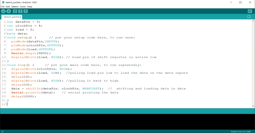
int dataPin = 3;
int clockPin = 4;
int load = 5;
byte data;
void setup() {                  // put your setup code here, to run once:
  pinMode(dataPin,INPUT);
  pinMode(clockPin,OUTPUT);
  pinMode(load,OUTPUT);
  Serial.begin(9600);
  digitalWrite(load, HIGH);     // Load pin of shift register is active low
}
void loop() {                   // put your main code here, to run repeatedly:
  digitalWrite(clockPin, HIGH);
  digitalWrite(load, LOW);      //pulling load pin low to load the data on the data inputs
  delay(10);
  digitalWrite(load, HIGH);     //pulling it back to high
  delay(10);
  data = shiftIn(dataPin, clockPin, MSBFIRST);  //  shifting and loading data in data
  Serial.println(data);         // serial printing the data
  delay(1000);
}
Output:
Here we have used a 74HC165 parallel in serial out shift register and connected its serial out (SO) pin to pin3 of the Arduino. Pin 4 of Arduino which is the clock out for IC is connected to clock (CLK) pin of the IC. Pin 5 of Arduino is connected to the load pin (SH/LD) pin of IC. Which is active low that means when it is low then it loads the data from data input pins of IC. As it loads the data the LSB of the data is available on the serial out of the IC at that moment. In our case data is 1111 0000 which is 240 in decimal. After loading the data this IC shifts the data at every clock pulse. That pulse is being provided to the IC from pin 4 of the Arduino. After shifting all data and loading it in the arduino we have printed that data on serial monitor.
shifOut() function in Arduino
shiftOut just do the reverse of shiftIn function. Where shiftIn function loads the serial data from any external source to Arduino, shiftOut function loads one byte data from Arduino to any external device serially. This function also have feature to set the bit order. Let’s see its syntax.
shiftIn(dataPin, clockPin, bitOrder, data)
Difference here is the data which we have to give it as fourth argument of the ShiftOut function. This is the data which will be shifted on the external device. DataPin will also be output here. Let’s see an example.
int dataPin = 3;
int clockPin = 4;
int shiftPin = 5;
void setup() {                  // put your setup code here, to run once:
  pinMode(dataPin,OUTPUT);
  pinMode(clockPin,OUTPUT);
  pinMode(shiftPin,OUTPUT);
  digitalWrite(shiftPin, LOW);
  shiftOut(dataPin, clockPin, MSBFIRST, 140);
  digitalWrite(shiftPin, HIGH);
}
void loop() {
  // put your main code here, to run repeatedly:
}
Output:
Here we have used the 74HC595 to serially load and parallel out the data. This IC also has a shift pin (ST_CP) which will load the data to output when a rising clock pulse occurs. So we have to toggle it when our data is shifted. For that we have first pulled it low and then start data shifting. After then we have to pull the shift pin high to actually show that data on output.
You made some really good points there. I checked on the net to learn more about the issue and found most people will
go along with your views on this website.