
Arithmetic logic unit is the very important unit inside a microcontroller or microprocessor. This is called the heart of any processor. As the name suggests, this digital device will perform arithmetic operations like addition or subtraction and logical operation like logical AND, OR or not. Now because this is a digital device so it will add or subtract binary numbers only. We call it ALU in short. Today you are gonna see that what is an arithmetic logic unit and what it does inside a processor.
Table of Contents
Introduction to the arithmetic logic unit
Modern ALU can perform the arithmetic and logical operations listed below.
- In arithmetic operation ALU does
- Add two numbers
- Subtract two number
- In logical operations ALU does
- Logical AND, OR, NOT or XOR
- Right or left shift a binary number
- Compare two number for equality or greater/less
Symbol of arithmetic logic unit
Now lets see that how we can represent the arithmetic logic unit on diagrams.
This is the block diagram of an ALU. In this block diagram the two numbers (integer operand) are the two inputs on which the operation will be performed. What operation should ALU perform on both number or even one number is set by the opcode. Status tells the ALU whether the output of previous operation should affect the current operation or not. You can ignore it for now. Result will be available at Y after an operation.
Algorithm to implement the arithmetic logic unit
We can implement the ALU using the algorithm below.
Here you can see the 1 bit ALU whose input operands are A and B. Which is also given to AND gate and OR gate. Those outputs are connected to inputs of multiplexer. We can select what should be appear on the output using select lines. So let’s build our own ALU which will perform operations like add, subtract, logical AND, logical OR and logical NOT. To build it we must have the knowledge of adders. So let’s see how adder works.
Half adder
Here ‘half’ word indicates that it will perform addition only on two bits. Let’s see how addition is performed using pictures and tables.
Now we will draw a logic diagram with the help of this table. We will find out Boolean function for sum and carry using K-map.
Boolean expression of sum for half adder
We can clearly see through the table that sum bit is following the truth table of XOR gate. Now let’s see it using K-map
Figure which shown above is the K-map for sum of half adder. Half adder have only two inputs X and Y, so there will four boxes in K-map as it is. Numbering of boxes is shown on the top left corner of all boxes. Now we will write the high sum output in the right boxes according to their numbering and try to make pair. Here you can see pairing is not possible.
So, the Boolean expression for sum is, S = X’Y + XY’. This is same as XOR gate, which means for sum bit we need to provide that input to XOR gate.
Boolean expression of carry for half adder
We can see in the table the carry bit is following the truth table of AND gate. Now let’s see it by K-map.
As you can see here also no pair is possible.
Boolean function, C = XY, which is same as AND gate
Logic circuit of half adder
You can see that for sum bit an XOR gate is implemented and for carry bit an AND gate is implemented as calculated.
Full adder
This adder can add 3 bits. Let’s know why we need the full adder. As we know the half adder can only add two bits, it can’t handle with carry. In the basic addition of two numbers a carry can arise, which is to be added in the next step. This means we need three bits adder which is this full adder. That is why this full adder is also called as complete adder.
Let’s see the truth table of full adder.
Now, we will find out Boolean expression for sum and carry using K-map.
Boolean expression of sum for full adder
In the full adder there are three inputs, so boxes in the K-map will be eight. Put the all 1 in the right box. So, Boolean expression of sum is,
S = X’Y’Ci + X’YCi’ + XY’Ci’ + XYCi
S = X’(Y’Ci + YCi’) + X(Y’Ci’ + YCi)
Boolean expression of carry for full adder
In this K-map there are three pair which are red, green and yellow.
Co = XY + YCi + XCi
Co = XY + (X + Y)Ci
Logic circuit of full adder
We can also implement full adder using half adder. By connecting two half adder as shown below we can implement the full adder.
Half subtractor
This subtractor subtracts two binary digits. It has two input through which we provides two binary bits and two output which are difference and borrow. We just have to apply two binary digits on its input and it gives either the difference or the borrow or both on outputs.
The truth table for half subtractor –
Now we have to find out the Boolean expression for difference and borrow.
Boolean expression of difference for half subtractor
As you can see the difference bit is same as sum bit of the half adder. So, Boolean expression will be the same as the sum bit.
D = X ⊕ Y
Boolean expression of borrow for half subtractor
There is only one high output on borrow output. Let’s see the input condition for that high output. The X input is low and Y input is high. So, the Boolean expression for the borrow output is –
B = X’Y
Logic circuit of the half subtractor
Here is the logic diagram of the half subtractor according to Boolean expression obtained.
Full subtractor
Full subtractor subtracts three binary digits and it handles with borrow. It has three input which are X and Y two binary bits and Bi (borrow in) and two output as half subtractor.
We will consider that Y bit is subtracting from X bit. So, let’s see the truth table of full subtractor –
Now we have to find out the Boolean expression for difference and borrow out.
Boolean expression of difference for full subtractor
The expression for the difference will be same as sum of full adder. So, the Boolean expression for the difference bit is –
D = X ⊕ Y ⊕ Bi
Boolean expression of borrow for full subtractor
Here you can see that there are three pairs which are red, green and yellow. So, let’s find out the Boolean expression for the borrow.
Bo = YBi + X’Y + X’Bi
Bo = YBi + X’(Y + Bi)
Logic circuit of the full subtractor
4 bit parallel adder
By connecting full adders in we can design a N digit parallel adder circuit. Here N represents the number of full adder. We will design a 4 bit adder, for that we need four full adders. It can add two binary numbers with 4 digits.
Similarly we can also design a N bit subtractor.
Carry look ahead adder (CLA adder)
It is a superior adder in comparison with full adder because it’s speed is better than a full adder. We will mention only carry bit. Suppose we have to add two large bits of number then it will take a lot of time for generating sum and carry due to its propagation delay.
Now see all the input condition for high carry output. If you noticed on last two high output then you will see that inputs X and Y are same and Ci is don’t care. So the expression will be Co=X.Y. now see the other condition, the expression will be (X⊕Y).Ci.
So, final expression will be Co=X.Y + (X⊕Y).Ci
Here X.Y represents the carry generator and (X⊕Y) represents the carry propagator. Say G is carry generator and P is carry propagator.
Then expression will be something like this Co= G + PCi
If our carry input is Cin-1 then carry output will be Cin, in that condition our expression will be Ci = G + PCi-1 or Ci = Gi + PiCi-1.
when i=0 then C0 = G0 + P0C-1 (equation 1)
when i=1 then C1 = G1 + P1C0 (equation 2)
Put the value of C0 from first equation
C1 = G1 + P1(G0 + P0C-1) = G1 + P1G0 + P1P0C-1
If i=2 then C2 = G2 + P2C1 (equation 3)
Now put C1 in the first equation
C2 = G2 + P2(G1 + P1G0 + P1P0C-1) = G2 + P2G1 + P2P1G0 + P2P1P0C-1
In the previous method we had to wait for the carry but in this method as you can see we need only C-1 carry so we can easily predict the output carry.
Making adder to subtract numbers using 2’s complement
We will design an ALU which will perform addition as well as subtraction. If we will use separate adder and subtractor for the both operations then our ALU design will be complex. So we have to find a way to manipulate adder circuit with may be some extra logic to perform subtraction. And actually there is a way to do this. That is by negating the second number and then adding it with first number. For example –
12 – 4 = 8
12 + (-4) = 8
2’s complement is a way to represent the negative number in binary system. We find the 2’s complement of a binary number is just by flipping all the bit and adding 1 o it. For example-
Let a binary number 1100 which is 12 in decimal. To find the 2’s complement we have to to invert it all the bits (that is called 1’s complement) and then add 1 to the obtained number. Let’s do that
1’s complement of 1100 is 0011 and after adding 1, it will be 0100 and it represents the -12.
So if we want to subtract 12 (1100) from 15 (1111) then we will write it as 15 (1111) – 12 (1100). The answer will be 3(0011) for this subtraction. We have seen that there is another way to so the same operation. For that we will use 2’s complement of the number 12 which will give use -12. Then we will add it to 15. Answer should be same as before in this way also.
As you can see that result is same for this operation also except the carry bit. But we don’t care about that.
Using XOR gate as conditional inverter
XOR gate has a property which is very useful for the case where you need to invert the bits of any binary number (1’s complement) under a condition. If you look at the truth table of the XOR gate then you will see that. Lets see that.
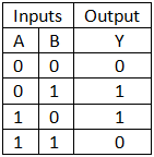
If you notice the both inputs and output then you will find that when A input is 0 then the output is as it is B. But when A input is 1 then output is inverse of B. We can use this property to flip the bits whenever we want.
Here when invert? = 0 then output will be A and when invert? = 1 then output will be A’. If you want to invert more bits then you have to add more XOR gate and joint all invert? signal.
2’s complement using XOR gate and full adder
Till now we have designed the logic to find 1’s complement, but we have to develop the logic to find the 2’s. For that we have to add 1 to the obtained 1’s complement. So that we have to use an adder to add 1. As you know that full adder has a carry in bit to add 1 from previous adder. We will use the carry in to add 1 to our 1’s complement from XOR output. That way we will obtain the 2’s complement and we can use all 4 bit of first operand of full adder. Circuit is shown below.
Our own arithmetic logic unit design
Here is the logical circuit of the arithmetic logic unit which will perform the addition, subtraction logical AND, OR and NOT according to algorithm that we discussed earlier.
What’s up to every body, it’s my first go to see of this blog; this web site carries amazing and really good stuff
designed for visitors.