In a battery powered electronics devices you often need to know the charge status of the battery. In this project we will create such circuit which can indicate the percentage of left energy in the battery. For indicating the charge percentage we will use LEDs. To drive the LEDs according to battery voltage, we can use LM3914 dot/bar display driver. The LM3914 is a monolithic IC that senses the analog voltage level on one of its input pin and drives 10 LEDs. We have to tell this IC about what is the voltage when battery is charged 100% and what is the voltage of battery when it is fully discharged. We can do it using the high and low reference voltage inputs present on its input. We don’t need the current limiting resistor because IC uses the constant current output which is programmable. Let’s see it’s application circuit given by the datasheet.
Table of Contents
LM3914 battery indicator circuit
This figure describes the wiring diagram of IC LM3914. First of all we have to power the IC by connecting the V– to ground and V+ to positive voltage. RLO, SIG and RHI determine how the LEDs should react to a voltage level. Where voltage on RHI pin determines the battery voltage when it is 100%. And RLO pin determines the voltage at which battery is fully drained. According to that data and SIG voltage IC determines which LEDs should glow and which LEDs should not. To understand it better, let’s see the internal diagram of LM3914 according to its datasheet.
Internal diagram of LM3914
As you can see that LM3914 has 10 comparators which compare the SIG IN voltage to voltage between RHI and RLO at 10 different values having same interval. These 10 voltages at same interval are created by those 10 1KΩ resistors. These resistors are acting like voltage divider and divide the voltage between RHI and RLO into 10 different values. Each voltage level is given to each of 10 comparators’ non-inverting terminal. Now SIG voltage is compared to these 10 values. Let’s say that a SIG voltage we have applied is above than 5 of those 10 values then 5 LEDs from bottom will glow.
You can change the RHI and RLO according to our battery discharge graph.
Drawbacks of this circuit
This circuit is not perfect battery indicator circuit. There are some drawbacks in this circuit such as we cannot set the RHI and RLO reference voltages while we are using only one battery. And second, major problem is that it shows the percentage of battery linearly but battery doesn’t discharge linearly.
This graph is for better understanding purpose and doesn’t contain actual data.
For small projects it can be used to indicate battery level. To improve it further, increase the RLO voltage to get more accurate percentage value.
For use the battery level indicator in an advance electronics project, we have to design another circuit for more accurate data.
Other applications of LM3914 IC
- As analog to digital converter (ADC)
- Music VU indicator
- Battery level indicator
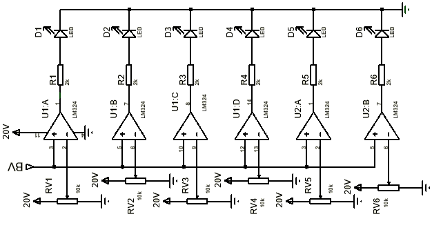
Circuit diagram of battery level indicator
Problem in the LM3914 circuit was that it was showing the linear decrease of battery voltage and it was occurring due to its internal 1kΩ resistor ladder. So, we will design our own circuit according to LM3914 and we will change the value of resistor according to our need. So, let’s see the circuit.
So, as you can see that this circuit is almost same as we saw in the internal diagram of LM3914. Difference is here that we replaced the constant resistor ladders with potentiometer and we have used only six LEDs to indicate charge level. Using those potentiometer we can adjust the trigger voltages of LM324 op-amps according to battery charge graph of our battery. For constant 20 volt we have to use a boost converter module.