Boost converter is a DC to DC step up converter. That means it converts any DC voltage to higher DC voltages. It doesn’t affect power much more so current will step down. Let’s say that we have 3.7 volts battery and we want to power a 5 volts device. In that case we need boost converter. It is widely used in electronics to safely power the electronics component. Widely used in the SMPS of the computers to create different voltage levels in using a single voltage source.
Table of Contents
Boost converter working principle
It also works on switching principle as buck converter. Components in this circuit is also same but there placement are different. Let’s see how they are placed.
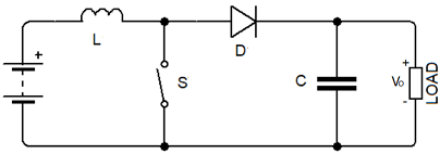
In this circuit when switch is closed then energy is getting stored in the inductor in form of magnetic field. When we open the switch this magnetic field starts collapsing and a voltage is induced across inductor. This voltage act like series combination with battery and voltage is boosted. Capacitor is used in this circuit for smoothing the output voltage. Diode is used to prevent the oscillation between the inductor and capacitor. Here energy stored in the inductor is proportional to how long switch was closed. This switching happens at very fast rate. We can’t switch it manually, so we replace the switch with MOSFET and give it a high frequency gate pulse. So, the output depends upon the duty cycle of pulse.
For a stable output voltage at any load we need to change the duty cycle every time when we change the load. Otherwise at different load output voltage will also be different at fix duty cycle. For this we need to design such switcher circuit and give it output feedback so that it can adjust its duty cycle.
Generating the PWM pulse for boost converter
There exists many specific IC for switching. But for better understanding first we will see how we can create such circuit without any premade IC. For this we will use op-amp and comparators. But before that we will see how we can generate the PWM signal.
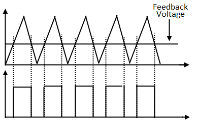
Logic for generating the PWM pulse is same as we saw in the buck converter project. In the waveform you can see that we triangle signal is compared with feedback voltage. Where triangle voltage is greater than feedback voltage output of comparator is high. So, triangular signal is connected to non-inverting terminal of comparator and feedback is connected with inverting terminal of comparator.
Now if output voltage decrease then feedback voltage will also decrease. Then duty cycle of comparator will increase, so the output voltage will increase then feedback voltage will also increase. This way output voltage stabilizes itself according to different loads. So, this increment and decrement of output voltage continues. This is why if you observe the output voltage is never smooth of any buck/boost converter.
Circuit diagram of boost converter
To make whole circuit without existing IC, we need following component.
- MCP602 op-amp
- Resistors
- Potentiometer
- Capacitors
- MOSFET driver (TC4420)
- MOSFET (IRL540)
- Inductor
- Diode
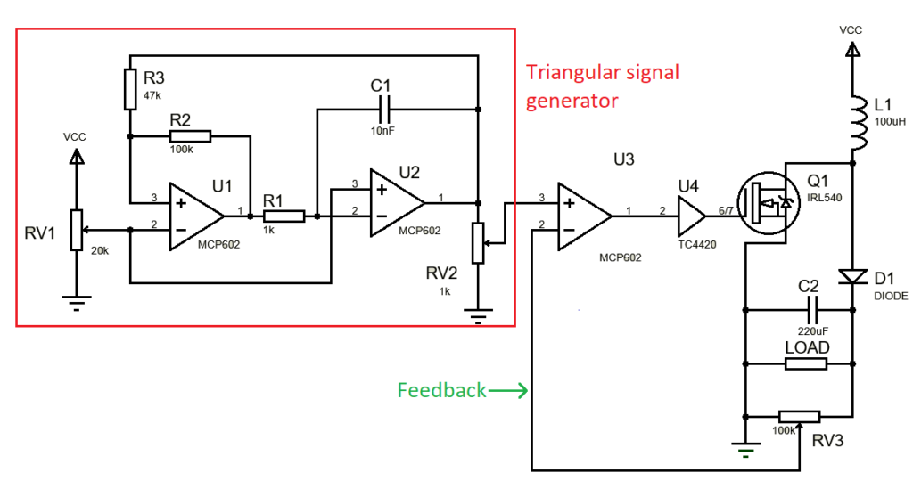
Figure shown above is the circuit diagram of boost converter without using any premade switching IC. As you can see the circuit looks very messy, complex and took a large space. This is why this circuit is not preferred.
Now we will design the boost converter using a specific switcher IC for boost converter. For this circuit we need following component.
- LM2577 DC-DC step up converter IC
- Capacitors (100uF and 1000uF)
- Inductor (100uH)
- Diode
- Potentiometer (100k)
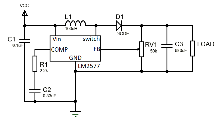
MOSFET switch is integrated in the IC. You can see how simple this circuit is looking. Just a few components compared to previous circuit. Its efficiency is also good compared to previous circuit. This is why this circuit is preferred. Don’t forget to use heat sink with the IC.
Applications of boost converter
- To regulate the power supply
- LED drivers
- Used in regenerative breaking of DC motor
- Used in SMPS of computer to create different voltage levels