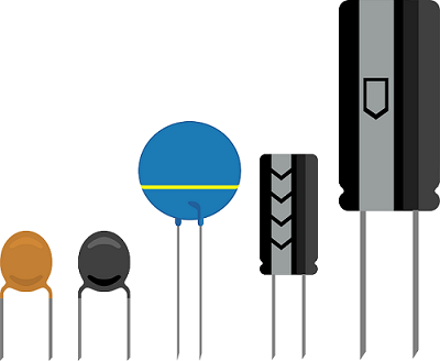
The capacitor is an energy-storing element like batteries. They are like a tiny rechargeable cells with very low capacity. The battery takes a long time to recharge and gives energy for a long time but in the case of capacitors, this charge and discharge process is quick.
Now you can imagine where we can use it. We can use it to compensate ripple in power supply, LC oscillator. It also works as a frequency-dependent resistor (capacitor reactance), so we can also use it in frequency filters. I have explained some applications below.
Table of Contents
Basic structure of capacitors
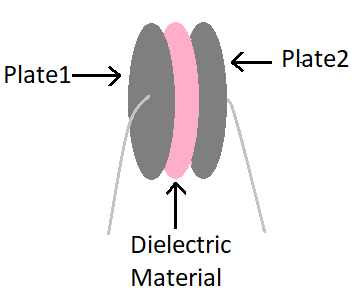
A capacitor is a body of two conductors separated by an insulator or air. The charges on the conductors are Q1 and Q2 and their potentials are V1 and V2 respectively. Often, in practice, the charge on two conductors are Q and -Q, and the potential difference V = V1 – V2.
We will only consider capacitors of this type of configuration. (A simple conductor can also be used as a capacitor if the other is assumed to be at an infinite distance) Both conductors can be charged by connecting two terminals of a battery.
Q is called the charge of the capacitor, although, in reality, it is the charge on a conductor of the capacitor – the total charge of the capacitor is zero. The electric field charge in the area between the plates is proportional to Q.
This charge is the reason behind the capacitor blocking DC and passing AC through it.
When we connect it to the DC power supply electrons accumulate on the plate which is connected to the negative terminal and get sucked from another plate. This process goes on until the electric field across plates reaches as same as the voltage of the battery. In this process, it seems that a current is flowing through the capacitor. The charge still remains on the plates. This way capacitor blocks dc and stores charge.
In the case of AC, this accumulation and sucking of the electrons go on continuously, so AC doesn’t get blocked.
Basic formula and measurement of capacitance
That is, if the charge on the capacitor is doubled, the electric field will be doubled at each point. (This is followed by Coulomb’s law and imposition principle of the reciprocal ratio between the underlying electric field and the charge.)
Now, the difference V is the amount of work done by each small positive charge in moving a small test charge from the conductor 2 to 1 against the field is equal. As a result, V is also directly proportional to Q and the ratio Q/V is a constant –
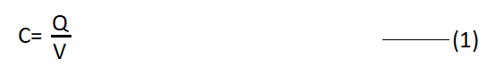
Here C is a constant which is called capacitance. Capacitance C does not depend on charge Q or potential V, capacitance C depends only on the geometric configuration (shape, shape, separation) of a body of two conductors.
[As we shall see further, it depends on the nature of the medium that separates the two conductors i.e. The SI unit of capacitance is 1 farad = 1 coulomb per volt or 1F = 1CV-1.]
Equation (1) shows that if Q is fixed for large C, then V is small. This means that a larger capacitor can amplify a larger magnitude of charge Q at a smaller voltage V (supercapacitor concept). It has practical utility.
The presence of a strong electric field around the conductor at high potentials is inherent. A strong electric field can accelerate the charges generated by ionizing the surrounding air, which may partially neutralize them by reaching the heterogeneous charged conductors. In other words, the charge of the capacitor can be degraded due to the degradation of the insulating capacity of the medium between the two conductors.
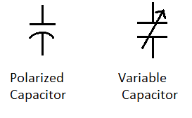
Symbol of capacitor
As we know the structure of the capacitor has two plates. Then its symbol should be such that it indicates two plates.

The image shown above is the symbol of the capacitor. You can see that it has two parallel lines which indicate both plates of a capacitor. Some different symbols are also used for different types of capacitors.
Unit and parameters of capacitance
The maximum electric field that a dielectric medium can tolerate without magnification (its anti-thermal properties) is called the parasitic strength of that medium. For air, it is about 3×10⁶Vm-1.
This area corresponds to a 3×10⁴V difference between the conductors for a 1cm grade separation between two conductors.
Therefore, for a capacitor to accumulate a large amount of charge without any corrosion, its capacitance must be so high that the potential difference or electric field between them does not exceed its fracture limit.
It can also be said in different terms, that a given capacitor has a limit to store charge without any significant corrosion.
In practice, 1 farad is a very large unit of capacitance, more common unit of capacitance, refractory to this unit (i.e. farad): 1µF=10-6F, 1 nF=10-9F, 1pF=10-12F etc. In addition to accumulating charges, capacitors are used as primary components in most alternating current circuits (ac circuits).
Parallel plate capacitor
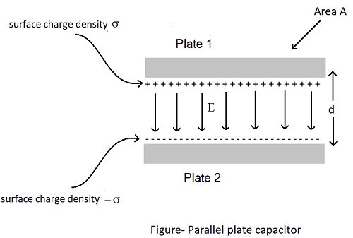
A parallel plate capacitor consists of two large plane parallel conductive plates parallel to each other, with less separation between them (figure shown below).
Suppose the area of each plate is A and the separation between them is d. The charge on both the plates is Q and -Q. Since d is much smaller than the linear dimensions of the plates (d2 <A), we can use the result of the electric field of the infinite plane sheet of uniformly charged surface density σ.
The surface charge density of plate 1 is σ=Q/A the surface charge density of plate 2 is -σ.
According to gauss theorem, the electric field is,
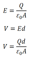
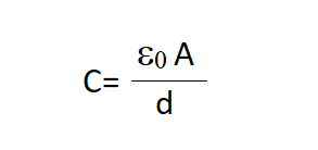
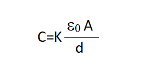
From equation (1), capacitance C=Q/V
Effect of dielectric on capacitance
Now see how the capacitance of a parallel plate capacitor is modified by the presence of a dielectric. As before, we also have two big plates, each with an area of A, separated by d distance from each other. The charge on the plates is ±σ, corresponding to the charge density σ (where σ = Q / A). When there is a vacuum between the two plates
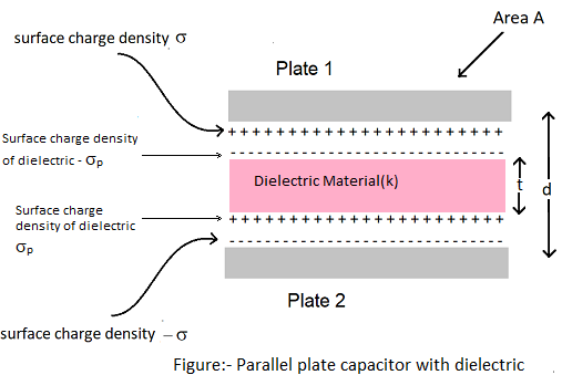
This case has capacitance C, after this, we consider the case in which all the area between the two plates has been filled by a dielectric. The entire dielectric is polarized by the field, and as explained above, this effect is equivalent to two charged sheets (perpendicular to the area on the pages of the dielectric) whose surface charge density is σp and -σp. In such a situation
Thus the reflectivity of a substance is a factor (> 1) by which when a dielectric material is completely filled between the plates of a capacitor, its capacitance value increases by a value of vacuum.
Combining capacitors
We have several capacitors whose capacities are C1, C2, . . . , Cn, By combining C, C, an effective capacitance can obtain the body of C. This effective capacitance depends on the way individual capacitors are connected. The two possible simple combinations are as follows.
Series combination of capacitors
The two capacitors C1 and C2 in the diagram are shown in series. As you can see that gap (d) of the equivalent series capacitors are adding up as we connect more capacitors in series. So equivalent capacitance of capacitors in series will decrease.
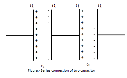
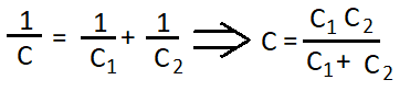
The formula to calculate total capacitance is given below,
The n numbers of capacitors in the diagram are shown in series
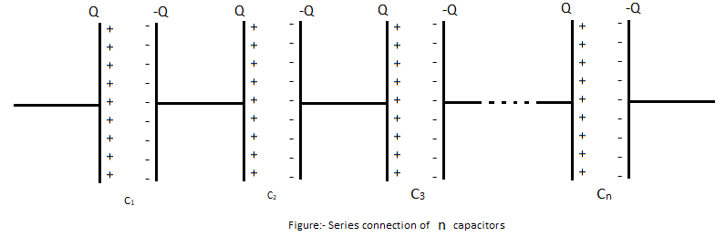
The formula to calculate the total capacitance of n numbers of capacitors in series is given below,
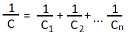
Parallel combination of capacitors
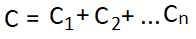
The n numbers of capacitors in the diagram are shown in parallel. As you can see that it seems that the area (A) of plates of every capacitor is adding up for equivalent parallel capacitors so capacitance will also add up for capacitors in parallel.
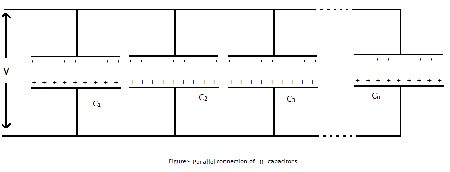
The formula to calculate the total capacitance of n numbers of capacitors in parallel is given below
Energy stored in a capacitor
As we know a capacitor is a device that stores energy. When we connect a voltage source across the two terminals of a capacitor, it gets charged. The potential difference across its terminal is the same as the voltage supplied to it. At this time some energy is stored in the capacitor.
Therefore, energy stored in a capacitor is
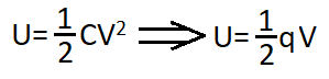
Here:
C= capacitance of a capacitor
V= voltage across plates
q=CV
Capacitor charging and discharging
In order to understand the capacitor well, we need to understand its charging and discharging graph.
Capacitor charging circuit
In circuit diagram shown below, the capacitor C is charging through resistor R1. Its charging time depends upon the value of the resistor and the capacitor itself.
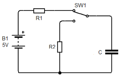
The capacitor will charge until the voltage across it is not equal to battery voltage (in this case 5v). The RC time constant of an RC circuit is the multiplication of resistor and capacitor value.
In charging condition, T = R1xC
Capacitor charging graph
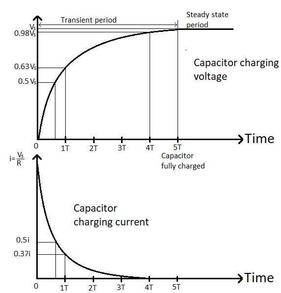
In this graph, the charging capacitor’s voltage and current are shown.
Capacitor charging circuit
In circuit diagram shown below, the capacitor C is discharging through resistor R1. Its discharging time also depends upon the value of the resistor and the capacitor itself.
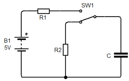
The capacitor will discharge until the voltage across it is not zero. The RC time constant of an RC circuit is the multiplication of resistor and capacitor value.
In thischarging condition, T = R2xC
Capacitor charging graph
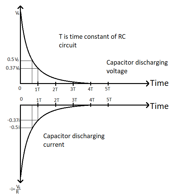
In this graph, discharging capacitor’s voltage and current are shown.
Application of capacitor
Power supply ripple filter
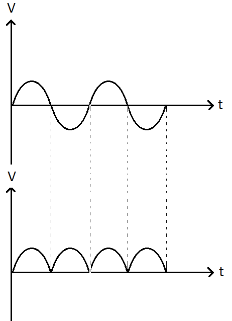
When an AC signal passes through a rectifier, it is converted into a dc signal. Thus, the achievable voltage is of half sinusoidal shape. Although it is unidirectional, its value is not constant. The graph is shown below.
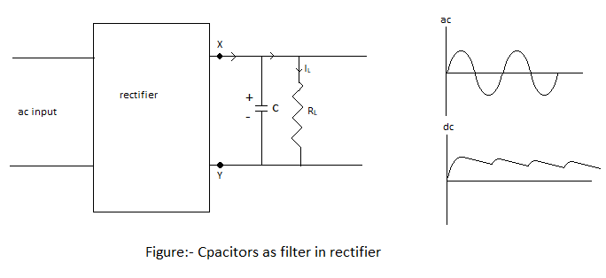
Usually, a capacitor is connected at the end of the output terminals (lateral to RL) to obtain the dc output from the pulsating voltage. To do the same, an inductor in a series of load RL can also be connected. Since they filter out the extra ripples and provide pure voltage, they are called filters.
Now we will discuss the role of capacitors in filtering.
When the voltage is increasing at the end of the capacitor, it is charged. If there is no external load in the circuit, it remains charged up to the peak voltage of the output. If there is a load in the circuit, it starts to dissolve through the load and the voltage at its ends starts to decrease.
In the next half-cycle of directed output, it is then charged up to its peak voltage. The rate of decrease in voltage at the ends of the capacitor depends on the capacitance C of the capacitor and the resistance product of the effective resistor RL which is called the blackout, in the circuit.
The value of C must be high. Therefore the output voltage obtained using capacitor input filters is close to the peak value of the rated voltage. Similar uses are widely used in power supplies.
Decoupling capacitors
For example, you are working with a microcontroller. If voltage is unstable means it drops for only a few moments. Then microcontroller will restart. This will be very annoying.
By using a capacitor we can power the microcontroller in that voltage drop condition. Then microcontroller will not get restarted. So, using decoupling capacitors we can filter out noise from the supply voltage.
Capacitor for this purpose is called “decoupling capacitor” and process is called “decoupling”.
Frequency filters
As I mentioned before capacitor also works as a frequency-dependent resistor which is denoted by XC. Its reactance is calculated by the formula given below.
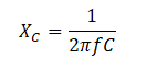
So, it is clear that capacitive reactance depends upon the frequency of the signal and its capacitance. As we increase the frequency of signal or capacitance the reactance will decrease.
Suppose you have a mixture of frequencies (like music), and we want to separate that frequency as our desire (for example we want to filter bass to our music). You need a circuit called a filter (In the case of filter bass from our music you need an active low pass filter). A filter is sort of a voltage divider whose division ratio depends upon frequency.
These three types of filters are widely used-
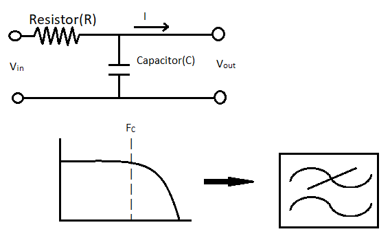
RC Low pass filter (LPF)
Low pass filter allows frequency below its cut-off frequency only. As in the circuit diagram you can see it looks like a resistor voltage divider where the resistor is acting like R1 and the capacitor is acting like R2. So, as the formula of the voltage divider, the output voltage will decrease as the reactance of the capacitor decreases. And reactance decrease with increasing frequency. So, as frequency increases output decreases. Here Fc is the frequency at which the output of the filter is 3dB less than the actual amplitude of the signal. we call it cut-off frequency. The formula to calculate cut-off frequency is-
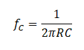
It is same for all filters.
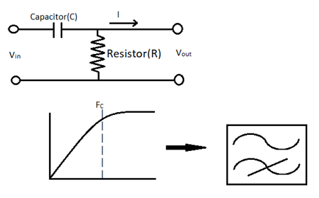
RC High pass filter (HPF)
High pass filter allows frequency above specified cut-off frequency only. As in the circuit diagram you can see it looks like a resistor voltage divider where the capacitor is acting like R1 and the resistor is acting like R2. So, as the formula of the voltage divider, the output voltage will decrease as the reactance of the capacitor increases. And reactance increases with decreasing frequency. So, as frequency increases output increases.
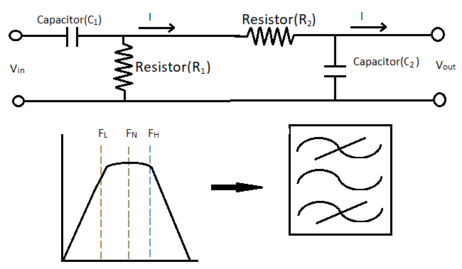
RC Band pass filter (BPF)
Bandpass filter allows frequency between two specified frequencies. It is a combination of low and high-pass filters. The circuit diagram and graph are shown below. Here FL is the lower cut-off frequency, FH is the higher cut-off frequency and FN is the center frequency.
These filters are called first order filters. For better damping of unwanted signals use higher order of the filter. A higher order filter can be made by connecting the filters in series or using an inductor instead of a resistor (LC filters).
Is it possible to know what is difference between ceramic capacitors and normal capacitors??
I will immediately grab your rss as I can not find your e-mail subscription link or e-newsletter service. Do you have any? Kindly let me know in order that I could subscribe. Thanks.