There are many types of amplifier. Class D amplifier is a type of them. It is very efficient amplifier (efficiency is up to 90-95%). This amplifier works on PWM technique. Audio signal applied to it first get converted into pulse width modulated signal and then it is amplified efficiently. After amplification it is converted back into original audio signal. To understand it better let’s first see the functional block diagram of class D amplifier.
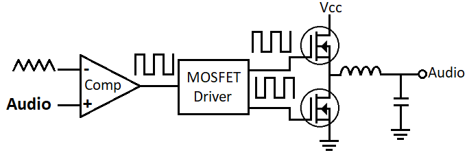
You can see that for creating PWM signal of audio signal, it is compared to a triangular signal using a comparator. Let’s see how it create PWM signal using a graph.
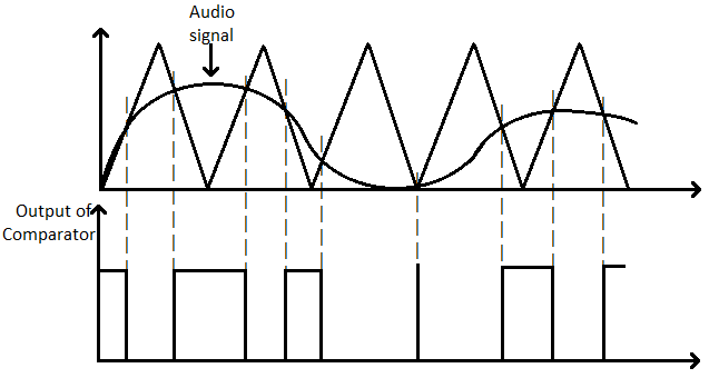
Frequency of triangular signal should at least 10 times of audio signal to recreate it again close to original signal. Triangular signal is connected with inverting terminal and audio signal is connected with non-inverting terminal of comparator. Whenever voltage of audio signal is below than triangular voltage then output of comparator is low and whenever voltage of audio signal is above than triangular voltage then output of comparator is high. This way we created very high frequency PWM signal equivalent to our audio signal.
We invert this signal using the inverter. Two MOSFETs are used as a switch and they driven by MOSFET drivers. Since MOSFET work as switch in its linear/ohmic region, voltage drop across its drain to source is very less and creates a very low power loss. So, this amplifier is very efficient.
After amplification we have to remove high frequency component. For this we will use LC low pass filter. We can use RC LPF but this will create more real power loss. Let’s see the circuit diagram of class D amplifier.
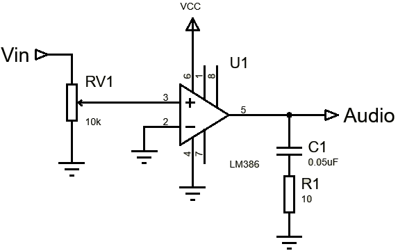
Circuit diagram of class D amplifier
To build this amplifier we need to generate a triangular waveform. For this we will use operational amplifiers. Then we need a comparator to compare the triangular waveform and audio signal. Then we need a NOT gate to invert the PWM pulses. Let’s see the list of component we need to build the circuit of class D amplifier.
- Three MCP602 op-amp
- Resistors (47kΩ, 100kΩ and 1kΩ)
- Potentiometers (20kΩ and 1kΩ)
- Capacitors (10nF and 1uF)
- IR2112 or IR2113 MOSFET driver
- Two IRL540 or IRLZ44N MOSFET
- Inductor (16.5uH)
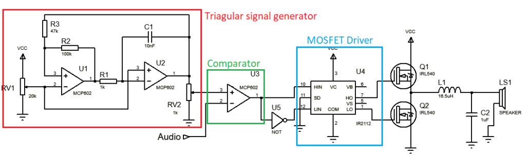
As you can see in the circuit diagram, we have used two op-amps to generate the triangular waveform. Using two potentiometers, we can adjust the waveform according to audio voltage. For better sound quality use a amplifier IC (LM386) in between the audio signal and comparator to increase voltage level of audio signal.
Then this waveform and audio signal is getting compared using a comparator. After comparing we get a PWM signal of audio signal. This PWM signal is inverted using a NOT gate. Then both signals go into the half H bridge MOSFET driver. This driver then drives two MOSFETs, which are amplifying the PWM signal efficiently. Then we have to recreate original audio signal. For this we will use LC low pass filter. To calculate the values of capacitor and inductor we need to do some calculations. We know that these formula from inductor and capacitor.
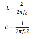
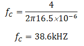
After rearranging the formula of inductor,

Now suppose, we are using a 4Ω loudspeaker, so Z=4 and we are using 16.5 mH inductor
After putting this cut-off frequency in the formula of capacitor,
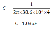
C= 1.03mF
This way we can calculate the values of inductor and capacitor.
This way you can create class D amplifier by yourself. Give it a try.
We stumbled oveer here different wweb page andd though
I might as well heck thing out. I like whaqt
I ssee so i am justt folowing you. Look forward tto looking into your
weeb pag for a second time.
I aam truly grateful to thhe holder off thiis weeb sijte
who haas shred thos greatt piece off writing aat
at this time.
Excellent beat ! I wish to apprentice while you amend your site, how can i subscribe for a weblog site?
Useful info. Fortunate me I discovered your website by chance, and I am shocked why this accident did not came about in advance! I bookmarked it.