Suppose you have a lot of sensors connected in your house and you want to control them with a microcontroller. But the problem here is that microcontroller have only few inputs and outputs. The solution for this problem is giving unique IDs (address) to all sensor. Let you have 3 sensors and you have not assigned addresses for them then you’ll need 10 input or output pins. But, if you encode and address them as binary numbers then it takes only three bits to create 8 different addresses i.e. 23 = 8. To encoding we use an digital logic circuit called encoder.
Encoder is a combinational logic circuit. It has more than one outputs and one or more than one inputs. Let’s say it has ‘n’ number of inputs and ‘m’ number of outputs. The relation between input and output will be n =2m. It make n digit of binary code to store 2n information. Where n digit is number of output and information is number of inputs. That means it number of inputs is 8 then the number of output will be 3.
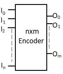
Figure shown above is an n✕m encoder. If any one of that input is connected to logic high, a m digit binary code will be generated at output according to that input and type of encoder. In normal encoder more than one input should not be high. Let’s see truth table and implementation of some encoders.
Table of Contents
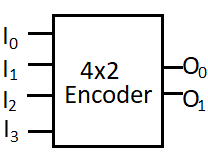
4×2 Encoder
This encoder will have 4 inputs and 2 outputs. It will generate two digit binary code which will be representing the input which is logic high.
Truth table
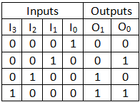
Boolean expression for O0 and O1:
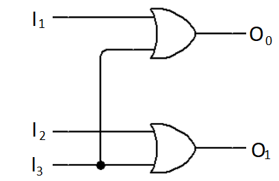
O0 = I2 + I3
O1 = I1 + I3
Now, on the basis of this expression we can implement the logic circuit for 4×2 encoder.
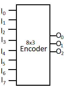
8×3 Encoder or octal to binary encoder
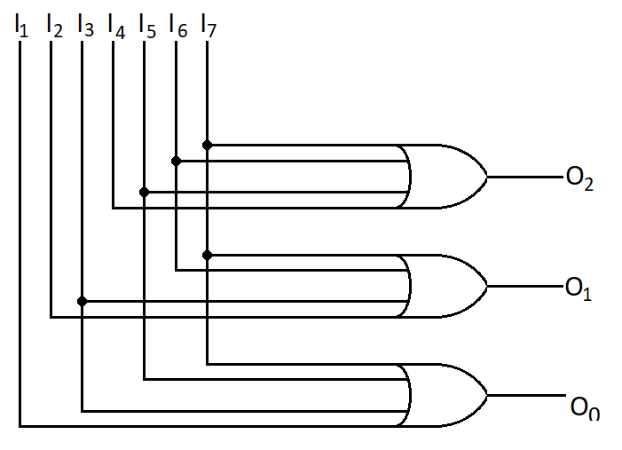
It has 8 inputs and 3 outputs. It is also called as octal to binary encoder. Because octal number system has also 8 number. Each input line correspond to each digit of octal number. It will generate three digit binary code corresponding to input line.
Truth Table
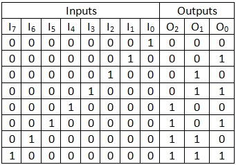
Logical expression O0, O1 and O2 using truth table.
O2 = I4 + I5 + I6 + I7
O1 = I2 + I3 + I6 + I7
O0 = I1 + I3 + I5 + I7
Implementation of logic circuit:
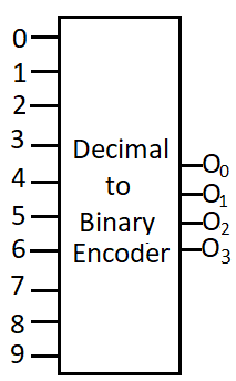
Decimal to binary encoder (10×4 Encoder)
It has 10 inputs and 4 outputs. It can have 6 more inputs but, we usually use it as decimal to binary encoder. Because decimal number system has also 10 number. Each input line correspond to each digit of decimal number. It will generate four digit binary code corresponding to input line.
Truth Table
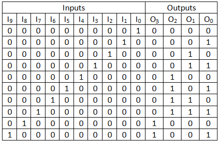
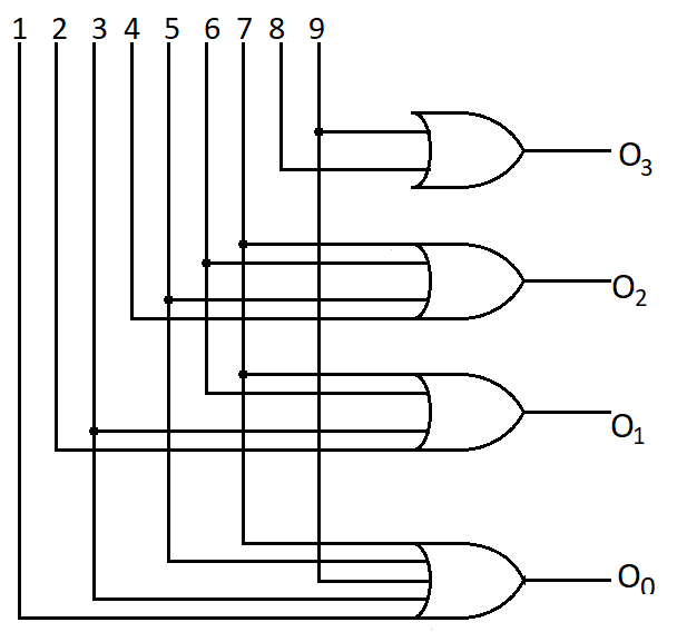
Logical expression O0, O1, O2 and O3 using truth table.
O3 = Σ(8, 9)
O2 = Σ(4, 5, 6, 7)
O1 = Σ(2, 3, 6, 7)
O0 = Σ(1, 3, 5, 7, 9)
Implementation of logic circuit:
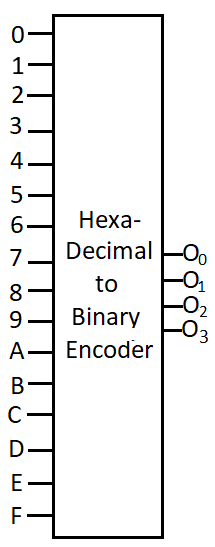
Hexadecimal to binary encoder (16×4 Encoder)
It has 16 inputs and 4 outputs. This is also called hexadecimal to binary converter. Because hexadecimal number system has also 16 number. It can be also used as decimal to binary encoder. Each input line correspond to each digit of hexadecimal number. It will generate four digit binary code corresponding to input line.
Truth Table
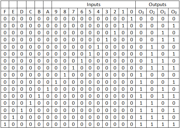
Logical expression O0, O1, O2 and O3 using truth table.
O3 = Σ(8, 9, A, B, C, D, E, F)
O2 = Σ(4, 5, 6, 7, C, D, E, F)
O1 = Σ(2, 3, 6, 7, A, B, E, F)
O0 = Σ(1, 3, 5, 7, 9, B, D, F)
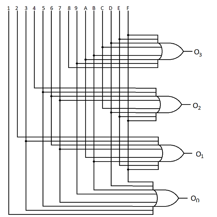
Implementation of logic circuit:
Priority Encoder
Let’s take previous example of the sensors connected in house. It may that some of those sensor are more prior than other and both triggers the encoder at same time. In that case sensor with more priority may get ignored. for example if a fire sensor and tank overflow sensor gets activated at the same time, in that case ignoring fire sensor may be very harmful. In that case priority encoder can help you. Priority level of each pin of priority encoder is different. For example, in a 4×2 priority encoder fourth pin has the highest priority and the first pin has lowest priority. That means if fourth and third both pin are active high then then its third output will get ignored since it has lower priority and output will be according to fourth input.
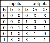
A 4×2 priority encoder has 4 inputs and 2 outputs, same as previous. This encoder has priority order on its input line. I3 has the highest priority and I1 has lowest priority. In the case when we press two or more button at the same time, output will be corresponding to the line which has highest priority.
Truth table for priority encoder
Let the priority order is: I3 > I2 > I1 > I0
K-map for O0:
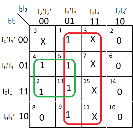
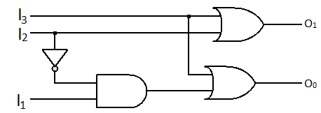
O0 = I3 + I2’I1
K-map for O1:
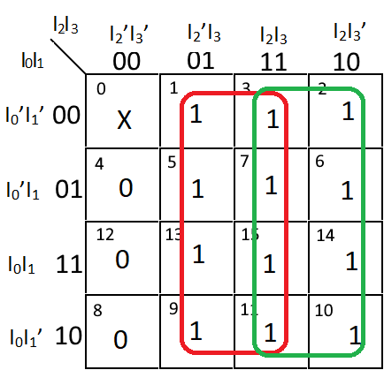
O1 = I3 + I2
Logic circuit implementation: