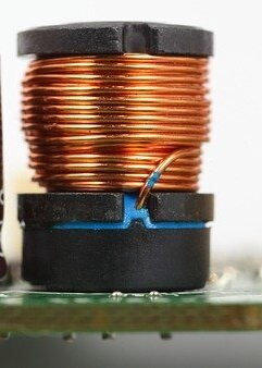
Inductors are also energy storing (passive) components like capacitors. Unlike capacitors which store energy in the form of electric field, inductors store energy in the form of magnetic field. It is a simple wire wound into a coil around a core.
As we know that current flowing through a wire develops a magnetic field around it, which is proportional to the current flowing through the conductor. We can find out the direction of the magnetic field according to current with the help of Fleming’s right hand rule. If we turn the wire into an inductor its magnetic effect will be more powerful. Let’s understand the working of an inductor by performing some experiments.
Table of Contents
Experiment 1- Drop a magnet through a copper tube
Take a copper tube (if you don’t have a copper tube you can take an Aluminum tube or wound Aluminum foil round). Now take a magnet that can pass through that tube. Now drop that magnet in that tube and notice its falling rate. You will notice that it is falling slower than its actual falling rate.
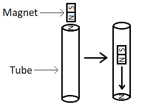
Explanation: – This happens because of electromagnetic induction. When a magnet moves around a conductor it induces EMF in that conductor, this is called electromagnetic induction. That will induce a current in that conductor.
This induced current will oppose the movement of the magnet. As mentioned before, the current passing through the inductor will make it a temporary magnet. The tube is acting as a closed loop inductor.
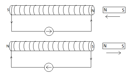
According to Lenz’s law inductor opposes any movement of magnet around it. So as we bring the magnet near the tube an induced current starts flowing which turns the tube into a temporary magnet. The pole of this magnetic field will be the same as the pole of the magnet coming closer to the tube, and opposite the pole of the magnet going away from the tube.
This way tube opposes the movement of the magnet. This is the reason behind slow falling rate of magnet.
Experiment 2- Boosting voltage
Take a 12 volt LED bulb, 9 volt battery, a push button, and an inductor. Connect it like shown in the figure below.
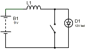
As we all know that a 9-volt battery can’t turn a 12 volt LED bulb. But if we push the button you can notice the led flickering.
Explanation: – The moment we push the button we will be connecting the inductor directly to the battery. Current starts to increase but the inductor resists the sudden change in current.
So, the inductor starts creating a magnetic field around itself proportional to the change in the current. This changing magnetic field induces an EMF in the same inductor that will oppose the current due to the battery.
This EMF resists its creator current from rising, so current rises slowly with respect to voltage (this is the reason behind 90° current lag in AC). As current reaches its peak then there is no change in current hence no change in magnetic flux also.
So, there is no opposing EMF acting on battery current and battery current flows freely. Now when we release the button then there is no current through the inductor, so the magnetic field starts collapsing. Because of this change in the magnetic field, a current will induce in the coil. This current will be pumped through the LED and it will glow until the magnetic field is not completely collapsed.
Experiment 2- Lighting up LEDs using coil and magnet
Take two LEDs and connect it in parallel but reverse to each other. Now connect its ends to the ends of a coil. Now move a magnet in and out of coil and you will see that each led is lighting up one by one.
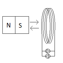
Explanation: – As we discussed previously that changing magnetic field causes changing magnetic flux. And changing magnetic flux through an inductor causes induction EMF across an inductor. That will induce a current in a close circuit.
So as we take the magnet closer to the coil, there is a change in magnetic flux around the inductor. It resists a magnet coming close by inducing a current which turns the coil into a magnet of the same polarity as that magnet that comes closer to coil.
This current also flows through that LED which is in forward bias according to the current and that one LED lights up. As we take magnet away from coil. It also resists magnet from going away by again inducing a reverse current which turns the coil into a magnet of opposite polarity of that magnet which is going away. This time current is reversed so other LED will light up.
Types and symbols of inductor
There are many types of inductors is available. They are categorized on the basis of the inner core type on which they are wound around and its shape. Their names and symbol are shown.
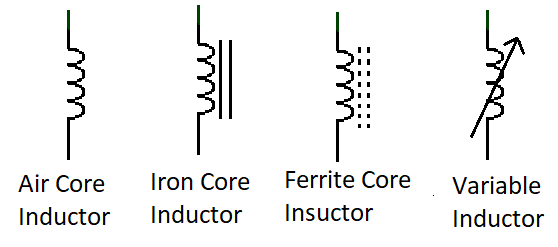
The inductance of an inductor depends on many factors such as the shape of a coil, the permeability, size and cross section area of core material, number of turns, etc. So inductor symbols are different according to their build properties.
Inductor equation
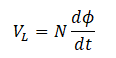
According to Faraday’s Law, any change in the magnetic flux in a coil produces a self-induced voltage. This induced voltage is also called back EMF.
Where:
N is the number of turns
Φis the amount of flux(unit- Weber)
t is time
Where:
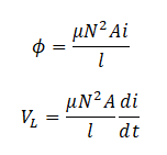
A is cross section area of the coil (m2)
μ is the permeability of core
l is the length of the coil in meter (m)
By substituting the ![]() with L (inductance of inductor (Henry)), we can calculate current and inductance.
with L (inductance of inductor (Henry)), we can calculate current and inductance.
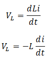
Here negative sign shows that induce EMF will be opposite to the applied voltage.
According to equation an inductor of one Henry will induce one volt when the current flowing through the inductor changes at a rate of 1 amp/sec. And if change in current is 0 which means current is steady in this case induced EMF will also zero. It will act like a short circuit (at very low resistance).
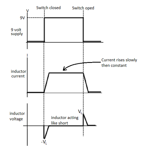
If you remember the experiment 2 we performed and I explained you. In that circuit with open switch, no current flows through the inductor. So change of current (di/dt) in that inductor will be zero. That means no induced EMF within the coil.
If we push that button current will start flowing through inductor. This current will slowly increase.
Now there is a change in the current. So there will be an induced EMF. This EMF can be calculated using Faraday’s Law. This EMF acts against applied voltage until the current reaches its maximum value.
Once the current reaches its maximum the inductor starts acting like a short circuit. And if we release the button current will start falling but, again inductor will fight against the change to keep the current flowing through the circuit by inducing a voltage. The same phenomenon is stated in Lenz’s Law. The Lenz’s Law states that: “the direction of an induced EMF will always oppose the change that is causing it”. You can understand better graphically.
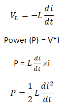
Power in an Inductor
We all know the voltage across the inductor.
Energy in an Inductor
We know that when current flows through the inductor, energy is stored in its magnetic field. An inductor has both positive and negative power in it. Integrating the power in an inductor gives energy that is always positive.

Where:
W is energy in joules
L is the inductance of the coil
i is current through the inductor
Filters using inductor
As we know that inductors show resistivity properties in AC signals. That is called impedance or reactance of inductor. We can calculate the cut-off frequency using this formula.
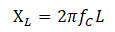
As you can see that it depends on frequency of the AC signal and the Inductance of inductor. If we increase the frequency of signal or inductance of inductor, impedance will also increase.
RL Low Pass Filter (RL LPF)
As we know that low pass filter allows the frequency below its cut-off frequency. Let’s see how we can build a low pass filter (LPF) using a resistor and inductor.
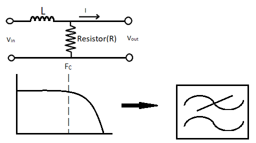
As you can see that by connecting the inductor in series and resistor in parallel with source we can design the RL low pass filter. Let’s understand the working of the RL low pass filter.
As in the circuit diagram you can see it looks like a resistor voltage divider where resistor is acting like R2 and inductor is acting like R1. So, as the formula of the voltage divider, the output voltage will decrease as the reactance of the inductor increases. And reactance decrease with increasing frequency. So, as frequency increases output decreases. Here Fc is the frequency at which the output of the filter is 3dB less than actual amplitude of the signal. It is called cut-off frequency. The formula to calculate cut-off frequency is-

RL High Pass Filter (RL HPF)
As we know that low pass filter allows the frequency above its cut-off frequency. Let’s see how we can build high pass filter (HPF) using resistor and inductor.
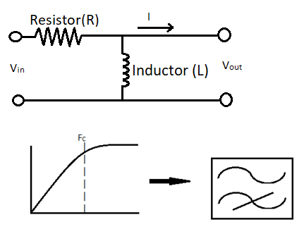
As you can see that by connecting the inductor in parallel and resistor in series with source we can design the RL high pass filter. Let’s understand the working of RL low pass filter.
As in the circuit diagram you can see it looks like a resistor voltage divider where resistor is acting like R1 and inductor is acting like R2. So, as the formula of voltage divider, output voltage will increase as the reactance of inductor decreases. And reactance decrease with increasing frequency. So, as frequency increases output decreases. Here Fc is the frequency at which the output of the filter is 3dB less than actual amplitude of signal. It is called cut-off frequency. The formula for calculating cut-off frequency is same.
RL Band Pass Filter (RL BPF)
It allows frequency between two specified frequencies. It is combination of low and high pass filters. Figure given below is the graph and circuit diagram of a bandpass filter. Here FL is lower cut-off frequency, FH is higher cut-off frequency and FN is center frequency.
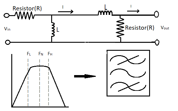
These filters are called first order filters. For better damping of unwanted signal use higher order of filter. We can make higher order filter by connecting the filters in series or using capacitor instead of resistor (LC filters).
Hello.This article was really fascinating, especially because I was browsing for thoughts on this issue last Wednesday.
It’s very simple to find out any topic on net as compared to books, as I found this article at this web site.|
Does your site have a contact page? I’m having a tough time locating it but, I’d like to shoot you
an e-mail. I’ve got some creative ideas for your blog you might be
interested in hearing. Either way, great website and I look forward to seeing it expand over time.
Yep! My website has a contact page.
https://electronics-fun.com/contact/
whoah this blog is fantastic i love reading your articles. Keep up the good work! You know, many people are hunting around for this information, you could help them greatly.
Hello very nice web site!! Guy .. Beautiful .. Wonderful .. I will bookmark your blog and take the feeds also?I’m glad to seek out numerous useful info here in the publish, we want develop extra techniques on this regard, thank you for sharing. . . . . .