To maintain steady output voltage from any power source we use linear voltage regulator. The circuits or devices which are very sensitive to voltage change uses this devices. Its resistance vary according to voltage and load attached to it. You can think it as a voltage divider circuit whose resistor can vary itself automatically according to input voltage and the load. We have seen buck converter and boost converter in previous articles. Those are called switching regulator because it uses an active device (transistor) that switches on and off to maintain the voltage at the output.
In case of switching regulator we have seen that it also amplifies the input voltage to higher voltage (boost converter) as well as it reduces the input voltage (buck converter). That means in switching regulator you can obtain output voltage even beyond the input voltage. But in the case of linear regulator input voltage should always greater than output voltage. It should not drop down below the output voltage that we want at the output at any point. For example if we have a voltage source that fluctuates up to 15 volts and down to 11 volts. Then we can regulate it to 11 volts. We can create a simple linear voltage regulator using Zener diode and resistors.
Lets see the types of linear voltage regulators.
- Shunt regulators
- Series regulators
- Fixed regulators
- Variable regulators
Table of Contents
Simple shunt voltage regulator
The shunt regulator creates a path from positive terminal to negative terminal of the power supply using a variable resistor. If we connect a load through the shunt regulator then current diverts from load resistance. This regulator is not that efficient since a small current always flows through the variable resistor also. We use this regulator for low power applications. Let’s see the circuit diagram of a simple shunt regulator.
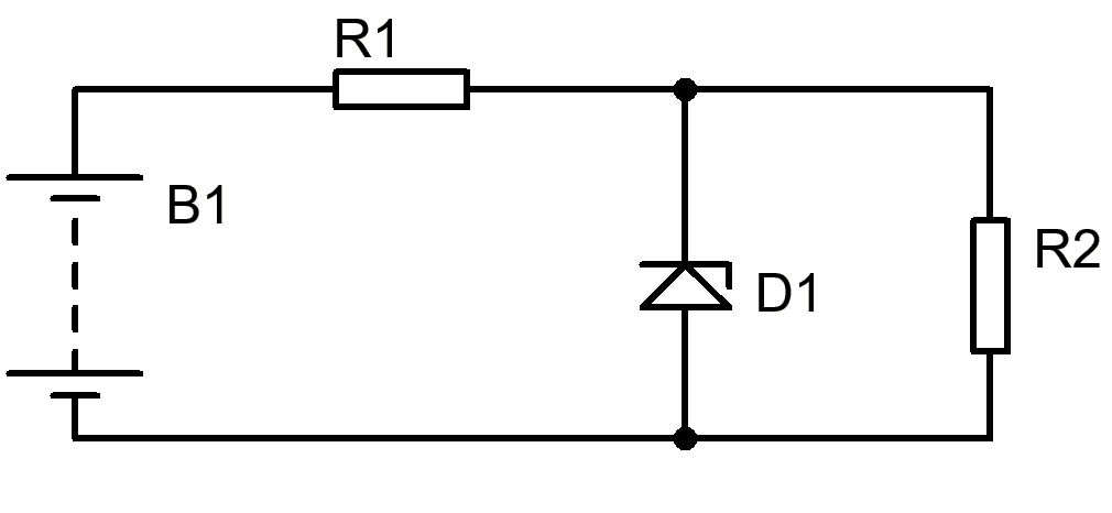
This is a simple shunt regulator with a Zener diode and two resistors (R2 is load resistance). Here Zener diode is the variable resistor. A Zener diode in reverse bias maintains the voltage across it by let the excess current flow though it in reverse direction. Here R1 supplies the current to both Zener diode and load resistance R2. When voltage increases then Zener diode let the current flow through it and that current also flows through the resistor R1 and excess voltage drops across R1. Let’s see the Zener diode VI characteristics to understand it better.
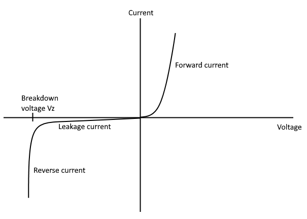
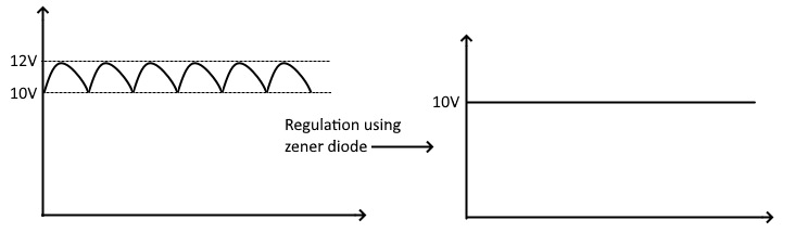
As you can see that in reverse bias when voltage exceeds the Zener breakdown voltage then a huge current flows in reverse direction. This is the property that we use to regulate the voltage of any power source. When reverse voltage across Zener diode exceeds the Zener breakdown voltage then reverse current starts to increasing. That results proportional voltage drop across resistor R1 and Zener diode itself. This way we regulates the voltage at output. See picture below.
You can calculate the value of resistor R1 using  where Vz is the Zener voltage and IR2 is the load current.
This type of regulator is used for very low power application and where load should permanently connected across the Zener diode. Removing load resistor may cause overcurrent through the diode and exceed its maximum current rating. That will damage the diode.
Simple Series regulator
Series voltage regulator is more efficient than shunt regulator. This regulator works by giving the path from supply to the load resistor through a variable resistor. This time variable resistor is a transistor as shown below.
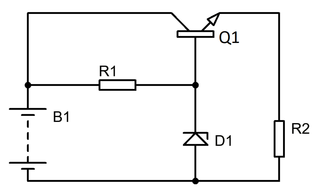
You can see that a transistor is connected in series with load resistor R2 and Its base is connected with Zener diode. So it is clear that transistor is in the emitter follower configuration. Now the load current for the Zener diode is the base current (IB) of transistor which is much smaller than resistor R2 as we have seen in shunt regulator.
You can calculate the value of resistor R1 as 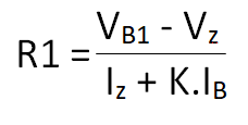 where Vz is the Zener voltage, IB (IR2/hFE(min)) is the base current, K = 1.2 to 2.
Now let’s see how a transistor works as a variable resistor. See the graph given below. It is the relation between input and output of a transistor.
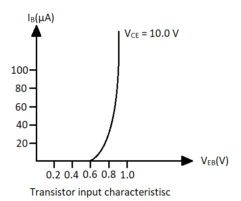
This graph shows the input characteristics of a common emitter transistor. Here input voltage is given to base and emitter ends and output is taken from collector emitter ends of transistor. As you can see that output current is increasing as input voltage is increasing. This means the collector emitter resistance decreases when base emitter voltage increases, but only to an extent.
In this regulator output voltage will be less than Zener voltage by 0.65 volts because of transistor’s VBE drop.
Fixed regulators
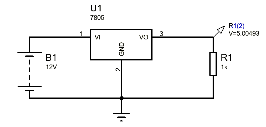
Fixed regulator comes in integrated package. It has three terminals and can generate fixed voltage of 3.3 volts, ±5V, ±6V, ±9V, ±12V, ±15V with maximum load current of 1.5A. There are two types of fixed regulators. First is the “78xx” series and other is “79xx” series. The “78xx” series (for example 7805, 7812 etc.) are used to regulate positive voltages and the “79xx” series (7905, 7912 etc.) are used to regulate negative voltages.
We can find out its regulated output voltage by last two digits of its part number. For example 7805 IC will regulate positive 5v and 7905 will regulate negative 5v. Circuit diagram of a regulator is shown below.
Variable voltage regulators
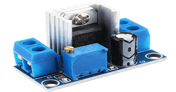
In variable voltage regulators we have LM723 for low power devices and LM317 for Medium power devices. These regulator features an adjust pin to adjust voltage at output. It can come with three or more than three pins with DIP (dual in-line) package. LM317 series regulates positive voltage and LM337 series regulates negative voltage with current capability of 7A.
We can adjust the output voltage by creating a voltage divider between the ground and it’s output. Divided voltage goes to the adjust pin of regulator. The ratio of division determines the output at the output. Let’s see the circuit diagram of LM317 regulator.
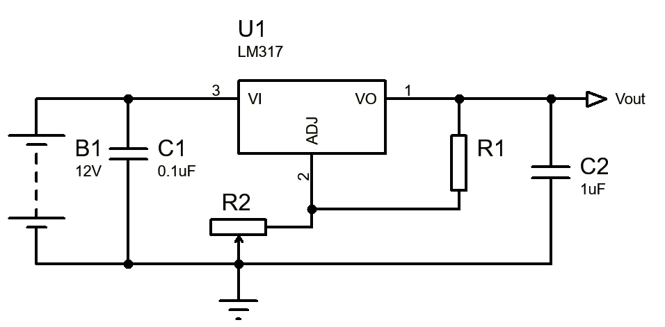
This is the Circuit diagram of a variable voltage regulator. Here by adjusting the R2 we can adjust the output voltage.
You can calculate the value of resistor R1 using 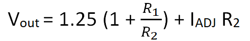 where Vz is the Zener voltage and IR2 is the load current.
Applications of linear voltage regulator
Linear voltage regulators are used in devices where a steady voltage is needed such as microcontroller or devices like that. We use it to create different voltage levels for different devices. Let’s take an example of Bluetooth enabled music system. In the system amplifier stage may need higher voltage as compared to Bluetooth module. So it is necessary to create a voltage level that is suitable for the Bluetooth module. This is the only one example. There can a lot more applications of the voltage regulator.
It’s good to know that a fixed regular comes in an integrated package. My husband was saying that he needs a new shunt regulator for work. He told me last night that he has to talk to his boss to see what kind he needs to get.