Long before the discovery of physical devices responsible for the flow of electric current in 1828 current G. S. Om discovered a fundamental rule related to current flow. Let a conductor from which the current I is flowing and suppose V is the potential between the ends of the conductor. Then Ohm’s law states that
V α I
or V = RI
Here the proportionality constant R is called the resistance (property of resistor) of the conductor. The SI unit of resistance is ohm and is denoted by the symbol Ω. Resistance R depends not only on the substance of the conductor but also on the expansion of the conductor.
| Resistivity of some substance |
| Substance | Resistivity At 0oC (Ω/m) |
| Conductor | |
| Silver | 1.6×10⁻⁸ |
| Copper | 1.7×10⁻⁸ |
| Aluminum | 2.7×10⁻⁸ |
| Tungsten | 5.6×10⁻⁸ |
| Iron | 10×10-8 |
| Platinum | 11×10-8 |
| Mercury | 98×10-8 |
| Nichrome | ~100×10-8 |
| Manganin | 48×10-8 |
| Semiconductor | |
| Carbon | 3.5×10⁻⁵ |
| Germanium | 0.46 |
| Silicon | 2300 |
| Non-conductor | |
| Pure water | 2.5×10⁵ |
| Glass | 1010-1014 |
| Hard rubber | 1013-1016 |
| Sodium chloride | ~1014 |
| Fused quartz | ~1016 |
Table of Contents
Limitations of ohm’s law
Although Ohm’s law is valid for a wide class of substances, there are some materials and devices used in electrical circuits where the proportionality of V and I does not apply. Broadly, this deviation may be of one or more of the following types.
(a) The proportionality of V ends with I (Figure below)
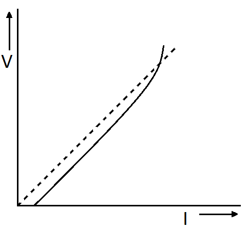
The dotted line represents the linear Ohm-law. The continuous line shows the relation of V and I for good conductors.
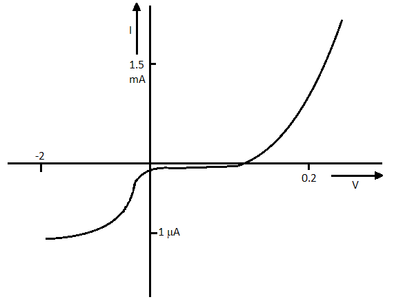
(b) The relation between V and I depends on the sign of V. In other words if the current I for something V. If, changing its direction by keeping the magnitude of V constant, no current of the same magnitude as I is produced in the opposite direction (Figure below). For example, the diode has this (see post for the diode) VI characteristic.
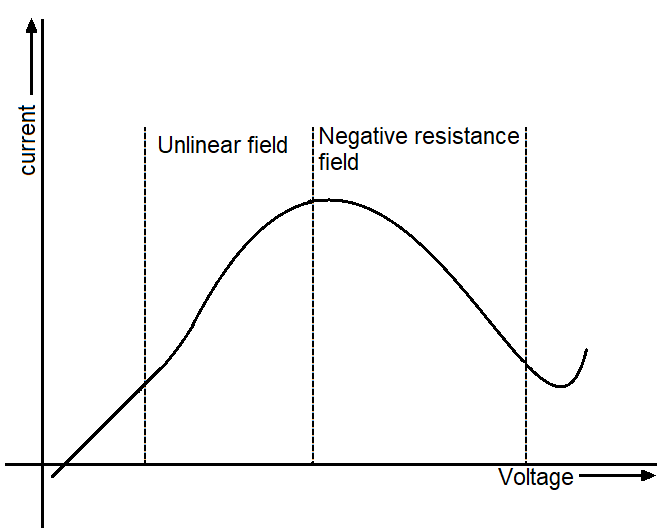
(c) The relation between V and I is not the only relation is that there can be more than one value of V for the same section I (figure below).
Resistor
A resistor is a device that is widely used in electronic circuits. They are used as current limiting or voltage dividers etc.
The range of these resistors ranges from a fraction of one ohm to a few hundred ohms. Resistors to the higher complex are made primarily of carbon. Carbon resistors are compact and inexpensive, so are widely used in electronic circuits. Carbon resistors are small in size, so their values are expressed by color codes.
Resistor symbol
In the figure below symbol of the resistor is shown.
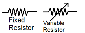
The resistor on the left side is a fixed resistor type, whose resistance is fixed and we can’t change. And resistor on the right side is a variable resistor type whose value we can change from and up to a limited value of resistance.
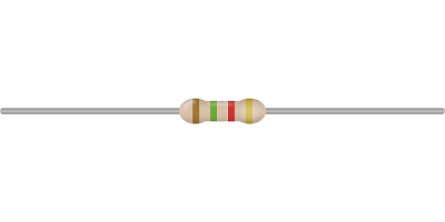
Resistor color code
If you have seen a resistor then you would know that it has some (generally four) color rings on its coax. These color rings tell us the value of resistance of a particular resistor according to its color. This is what we call a resistor color code.
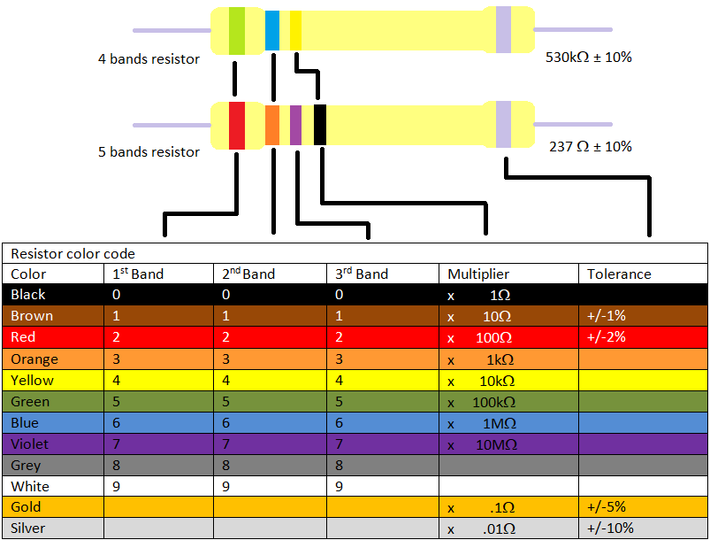
The coax on the resistor is a group of colored rings whose significance table above has been listed. The first two lines from the end direct the first two significant digits of resistance in ohms. The third string indicates the decimal multiplier (as listed in Table above) and the last row expresses the tolerance or the possible variance in the percentage of the directed value. Sometimes it is not the final stripe, which means that the tolerance is 20%. For example, if the four colors are orange, blue, yellow, and golden, then the resistance value would be 36×104Ω with a 5% tolerance value.
There is a trick to remember the resistor color sequence, remember this “B. B. ROY of Great Britain has Very Good Wife wearing GOLDen SILVER necklace”.
Combination of resistor
There are two types of resistor’s combination
i) Series combination of resistor
ii) Parallel combination of resistor
Formula to find out total resistance for a resistor in series and parallel is given below
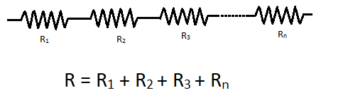
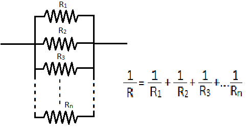
In the above figure, the resistor is in series, and a formula for calculating series resistance is given. As you can see the equivalent resistance of resistors in series is just the addition of resistances of all resistors. So the value of equivalent resistance increases when resistors are in series. And in the below figure resistor is in parallel and the formula for calculating parallel resistance is shown. As you can see the equivalent resistance of resistors in parallel is inversely equal to the inverse sum of all resistors in parallel. So the value of equivalent resistance decreases when resistors are in parallel.
Resistor for current limiting (Resistor for LED)
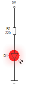
Normally an LED draws 20mA current at 2-3 volts. If the input voltage across an LED is less than 3 volts then it will glow properly. As the voltage increases, the LED will draw more current which means the probability of the LED going bad will increase. To overcome this problem, a current limiting resistor is connected in series with the circuit.
According to ohms law, if a 5v battery is connected to a LED and we want that led should draw only 20mA current, we have to adjust the resistivity of the wire.
Let’s see what value of resistor is,
V = 5v
I = 20mA that means 0.02A
Ohm’s law,
V=IR
5v = 0.02xR
R = 250 Ω
So, by adding 250 Ω resister we can protect our LED.
Voltage divider
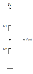
The voltage divider is a resistor arrangement circuit that can give us fraction voltage (divided voltage) of its input voltage as output. It turns a large voltage into a small voltage. Using just two resistors we can draw a circuit to divide the voltage which is shown above.
Here is the formula for calculating output voltage,
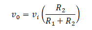
A good example and application of a voltage divider is a potentiometer.
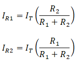
Current divider
The current divider is a circuit that divides the current into two or more parts. We can make a basic current divider using two resistors as shown.
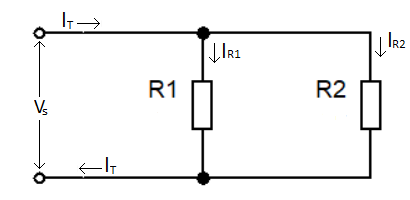
The current in both resistors is equal to the total currents in the circuit. So, we can write it as
IT = IR1 +IR2
We can find the current in the resistor by using this formula
Conclusion
You saw how a resistor functions in electronic circuits. How we can protect any component from high voltage or current. You have seen how to read the resistor value and formulas to calculate the equivalent resistor connected in different configurations. Voltage and current divider are explained.