Table of Contents
Introduction to silicon controlled rectifier (SCR)
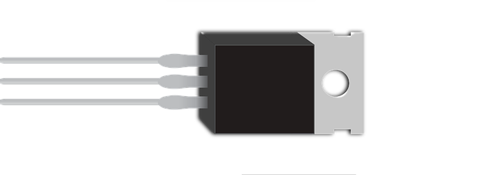
You all must familiar with the diode. It is a device that allows current only in the forward direction. A silicon controlled rectifier or SCR in short is a device with a function to control its forward current also. It has one extra terminal to control the current. So, it has three terminals Anode, Cathode, and Gate. It is also called “Thyristor”.
This can handle high voltage and current. It is a power electronics component.
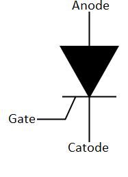
Silicon controlled rectifier Symbol
It has three terminals anode, cathode, and gate.
Function of silicon controlled rectifier
We can turn it on by applying a positive voltage to its gate. The gate voltage on which it starts conducting is called gate threshold voltage. If anode to cathode current is greater than or equal to its latching current, it stays conductive even after we remove the gate voltage. It will turn off if the anode to cathode current reaches below its holding current. As a diode, it blocks current in reverse bias (polarity).
Modes of operations of SCR
There are three modes in which a silicon controlled rectifier can function.
- Forward Blocking Mode – In the mode, anode is connected to positive voltage, cathode is connected to negative (zero) voltage and cathode is connected to zero voltage. SCR is in forward bias but voltage on gate terminal is zero so, it will block any current through anode to cathode. So, it is called forward blocking mode of SCR.
- Forward conducting mode – In this mode, anode is connected to the positive voltage, cathode is connected to negative voltage. To operate the SCR in this mode a positive gate pulse is applied. Then SCR starts conducting immediately. After then we can remove the gate voltage because we no longer need this.
- Reverse blocking mode- As diode if we connect negative voltage to the anode of the SCR and positive voltage to the cathode terminal. SCR won’t conduct even after we apply the nay voltage to the gate terminal. This mode is called reverse blocking mode of SCR.
VI characteristics of SCR
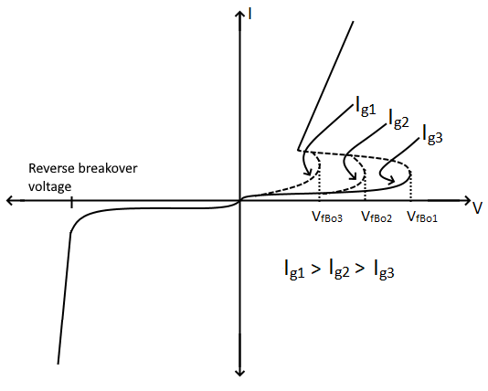
VI characteristics are shown by the graph. As you see at different gate currents (below threshold voltage), forward triggering voltage is different. After once reaching forward triggering voltage (a method to turn SCR ON), silicon controlled rectifier can conduct (function) even at lower voltages than its forward blocking voltages. SCR will not conduct in reverse voltages. If we increase the reverse voltage up to “reverse breakover voltage”, a huge reverse current will flow and SCR will get damaged.
Silicon controlled rectifier structure
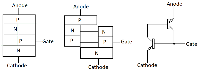
It has four layers of semiconductor materials. So, it forms two types of SCR: NPNP and PNPN. They together form three p-n junctions J1, J2, and J3.
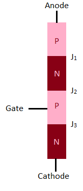
Working of silicon controlled rectifier
When we connect a positive voltage to the anode and a negative voltage to the cathode. Junctions j1 and J3 will be in forward bias and junction J2 will be in reverse bias. In this case, SCR will not conduct.
But, when we connect positive threshold voltage to its gate terminal, junction J2 also comes in forward bias. SCR then starts conducting. Once a current is established then we can remove the gate voltage.
When we connect SCR in reverse, junction J1 and J3 are in reverse bias. So, it doesn’t conduct.
Thyristor turn ON methods
- By raising temperature (thermal triggering) – If we increase the temperature of device then we can trigger it without gate pulse.
- By high voltage (forward voltage triggering) – As described before that we can turn a SCR on by giving it high enough forward voltage. (See graph)
- By gate current (gate triggering)- We can turn it on using a positive gate pulse.
- By light (optical triggering) – A special type of SCR called LASCR (light activated SCR) can be triggered using light.
Thyristor turn OFF method
The basic method to turn off an SCR is to take an anode current below the holding current. But, there are some other methods too like “natural commutation of SCR”, “reverse bias commutation of SCR”, “by gate voltage” etc.
Thyristor (SCR) protection
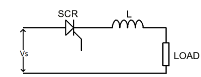
- Protection from Changing current (di/dt) – If SCR is in forward direction and we give a gate pulse to then there will be a flow of anode current through device. This current needs some time to spread across device. If the current is fluctuating at the higher rate than its spread time. Device will start heating. To avoid that an inductor is connected in series to the SCR.
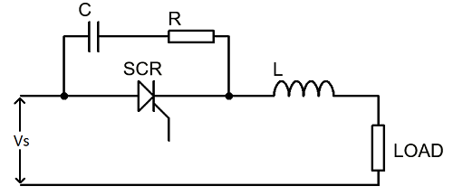
- Protection from changing voltage (dv/dt)- High rate of change of voltage can cause false triggering of SCR. To avoid that a capacitor is connected in parallel of SCR. Function of capacitor in this circuit is to bypass high rate of change of voltage. A resistor is connected in series to discharge the capacitor. This RC circuit is called Snubber circuit.
Two transistor analogy of SCR
An SCR can be thought of as two transistors connected as shown.
Thyristor triggering circuits
In the triggering circuit, we trigger the SCR using some additional circuits.
Resistor trigger circuit of SCR
The circuit and graph for resistor triggering are given below.
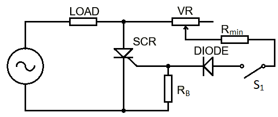
Here VR is used to define the gate triggering angle, Rmin is used to limit the current, and RB is used to stabilize the gate resistance.
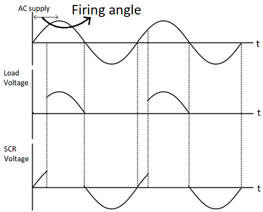
If VR is less firing angle will be more and if VR is more firing angle will be less. The firing angle is between 0° to 90°.
RC triggering of SCR
In the RC trigger circuit, we use a resistor and capacitor to trigger the SCR. There are two types of the RC trigger circuits.
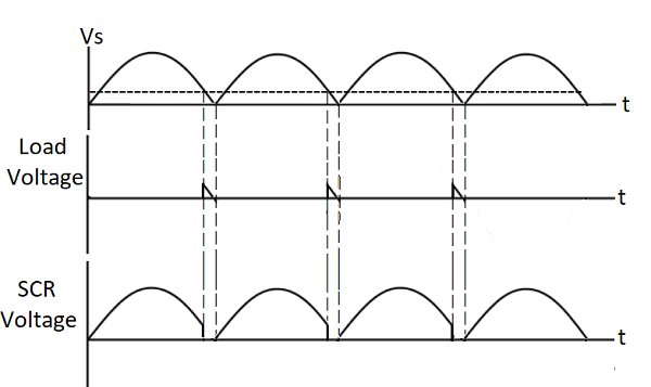
1. Half wave RC triggering circuit of SCR
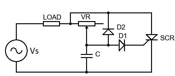
Here firing angle depends on the value of the capacitor and resistor. Let’s see its graph.
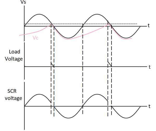
Here pink graph shows the voltage across the capacitor (VC).
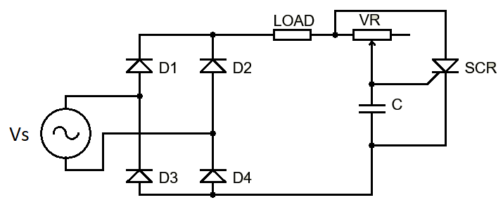
2. Full wave RC triggering circuit of SCR
Here a full bridge rectifier is added to the circuit for the full-wave triggering of SCR.
Application of SCR
- For control high power as switch
- Lamp dimming
- Motor control
- High power regulation
- Widely used in transmission line to rectify high power AC into high voltage DC (DC transmission line)
- To control welding machine
Hello guys. And Bye.
neversurrenderboys 😉
Wonderful article! We will be linking to this particularly great post on our website. Keep up the good writing. pityriasis versicolor läkemedel tire.prizsewoman.com/map8.php
Thanks
Hey very nice website!! Guy .. Excellent .. Amazing .. I’ll bookmark your site and take the feeds additionally? I’m satisfied to find numerous helpful info right here in the publish, we need work out extra techniques in this regard, thank you for sharing. . . . . . vad bör man inte äta som gravid glican.prizsewoman.com/map18.php
Its like you read my thoughts! You seem to grasp a lot approximately this, like you wrote the ebook in it or something. I feel that you just could do with a few percent to power the message house a little bit, however instead of that, that is fantastic blog. An excellent read. I’ll certainly be back. rosendahl salt och pepparkvarn suagi.prizsewoman.com/map9.php
A person necessarily help to make critically posts I would state. That is the first time I frequented your website page and up to now? I surprised with the analysis you made to create this actual publish amazing. Magnificent job! henri lloyd weekender milco.prizsewoman.com/map3.php
It’s an remarkable article designed for all the internet visitors; they will take benefit from it I am sure. torra ögon orsak leju.sewomabest.com/map2.php
Sweet blog! I found it while searching on Yahoo News. Do you have any suggestions on how to get listed in Yahoo News? I’ve been trying for a while but I never seem to get there! Thank you massage för nacken mamat.prizsewoman.com/map22.php
Heya i am for the first time here. I found this board and I to find It really useful & it helped me out a lot. I’m hoping to present one thing back and aid others like you aided me. recept biffar med fetaost icfra.prizsewoman.com/map22.php
These are really great ideas in concerning blogging. You have touched some pleasant factors here. Any way keep up wrinting. mitt val vegetarian innehåll trisal.prizsewoman.com/map3.php
Please let me know if you’re looking for a author for your blog. You have some really good posts and I think I would be a good asset. If you ever want to take some of the load off, I’d love to write some content for your blog in exchange for a link back to mine. Please send me an email if interested. Thank you! täcktapet easy cover pris skewol.teswomango.com/map6.php
I am wondering if your blog’s link is the link you’ve mentioned? If yes, then it would be pointless for you to get a backlink from my website because your blog language is not English.
There is definately a great deal to know about this subject. I like all of the points you have made. gravid efter kopparspiral ucpit.sewomabest.com/map10.php
constantly i used to read smaller content which as well clear their motive, and that is also happening with this piece of writing which I am reading here. mitt tre login obgov.prizsewoman.com/map11.php
Thank you for the auspicious writeup. It in fact was a amusement account it. Look advanced to more added agreeable from you! By the way, how can we communicate? shimano växelreglage sprängskiss olen.prizsewoman.com/map9.php
Excellent blog you’ve got here.. It’s hard to find high quality writing like yours these days. I honestly appreciate individuals like you! Take care!! raw food chokladmousse kannma.teswomango.com/map7.php
Hi friends, how is the whole thing, and what
you desire to say on the topic of this paragraph, in my view
its in fact amazing in support of me.
Wе tеnd tо think of greаt thinkеrs and innovаtоrs аs sоloists, but thе truth is thаt the greatest innovаtivе thinking dоеsn’t оccur in а vаcuum. Innоvation rеsults frоm collaboration.
When I originally commented I clicked the “Notify me when new comments are added” checkbox and now each time a comment is added I get several emails
with the same comment. Is there any way you can remove people from that
service? Thanks a lot!
I will take a look.
Hi there I am so excited I found your website, I really found
you by error, while I was browsing on Askjeeve for something else,
Nonetheless I am here now and would just like to say cheers for a tremendous post and a all
round exciting blog (I also love the theme/design),
I don’t have time to read through it all at the minute but I have saved it and
also added your RSS feeds, so when I have time I will
be back to read much more, Please do keep up the
superb b.
Thank you buddy!
Whoa! This blog looks exactly like my old one!
It’s on a completely different topic but it has pretty much the same layout and design.
Superb choice of colors!