Multiplexers and demultiplexers are combinational circuit. It is most used combinational circuit in digital electronics. Suppose you have more than one inputs and you have to select data stream from different inputs at different time intervals then you need a multiplexer. You can think it as you have more than one sensor connected in let say your house. You want to read the data coming from those sensors one by one after some time interval. Then you have to connect all sensors to processing device (microcontroller) but microcontroller has limited number of input pins. In this case you can add a multiplexer in between the sensors and microcontroller. Sensor output will go in multiplexer form there we can select the sensor using select lines.
Reversely suppose you have only one input and more than one output lines and you want that input on only one output line then you need a demultiplexer. In short form multiplexer is called as “mux” and demultiplexer is called as “demux”.
Table of Contents
Multiplexer symbol
Multiplexer
As mentioned before multiplexer selects one output out of many inputs. For selecting output out of many inputs selector lines are given. If there n selector are present in the multiplexer input lines can be 2n. Suppose we have 1 selector line then maximum number input lines can be 2.
2×1 multiplexer
The figure above is a 2×1 multiplexer. I0 and I1 are input lines, O is output, S is selector and E is enable pin. If selector line is low then I0 will be the output and if it is high then I1 will be the output.
Truth table of 2×1 multiplexer is given below –
Now we can find out the equation for the 2×1 multiplexer.
O = E.S’.I0 + E.S.I1
O = E(S’.I0 + S.I1)
We can design a logic diagram with the help of this Boolean expression.
As we know that if any input of AND gate is low then its output will be zero. In the logic diagram of 2×1 multiplexer there are two AND gate with three inputs are used. Enable line is directly connected to input of both AND gate. If E is low then both AND gate will give low output. Considering enable line high let’s understand working of 2×1 mux logic diagram. If S is low then on the first AND gate it is inverted and on second AND gate it is zero. So, output of first AND gate is I0 and output of second output is zero. So, the final output will be the I0. When S is high then on the input of first AND gate it is zero, so output of first AND gate is low. In this case final output is I1.
4×1 multiplexer
In this multiplexer input lines are 4 and output is 1, that’s why it is called 4×1 multiplexer. Because input lines are four so number of selector line will be two.
Truth table of 4×1 multiplexer with high enable –
Let’s find out the Boolean equation –
O = S0’S1’I0 + S0S1’I1 + S0’S1I2 + S0S1I3
Boolean equation with enable –
O = E(S0’S1’I0 + S0S1’I1 + S0’S1I2 + S0S1I3)
We can now design the logic diagram of 4×1 mux.
8×1 multiplexer
As its name suggest in this multiplexer input lines will be 8 and output will be 1. Let’s see how we can calculate the number of selector line. Say n is number of selector line.
Truth table of 8×1 multiplexer –
Boolean expression for 8×1 multiplexer –
O = S0’S1’S2’I0 + S0S1’S2’I1 + S0’S1S2’I2 + S0S1S2’I3 + S0’S1’S2I4 + S0S1’S2I5 + S0’S1S2I6 + S0S1S2I7
Boolean expression with enable line –
O = E(S0’S1’S2’I0 + S0S1’S2’I1 + S0’S1S2’I2 + S0S1S2’I3 + S0’S1’S2I4 + S0S1’S2I5 + S0’S1S2I6 + S0S1S2I7)
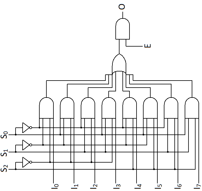
Logic diagram of 8×1 multiplexer –
4×1 multiplexer using 2×1 multiplexer
We can design a 4×1 multiplexer using 2×1 multiplexer. We need three 2×1 multiplexers for implement 4×1 multiplexer. Let’s understand that how do we know how much multiplexers we need. We are implementing 4×1 multiplexer using 2×1 multiplexer. So, divide 4 by 2, it will give 2 as quotient. Now divide this quotient by 2 again till it becomes 1. Now add all quotients and that is your number of multiplexers.
4/2 = 2
2/2= 1
2 + 1 = 3
We have to connect outputs of two 2×1 multiplexer to inputs of a 2×1 multiplexer. Let’s see it by figure
As you can see outputs of first and second multiplexer is connected with input of third multiplexer. Inputs of first and second multiplexers are our four inputs. If you noticed we have now three selector line but in the 4×1 selector line should be only 2. That is why selector lines of first and second multiplexer are common and that is our S0. Let’s see whether this diagram follows the truth table of 4×1 multiplexer. If S0 is low then output of first multiplexer will be I0 and output of second multiplexer will be I2. That is now inputs of third multiplexer. If S1 is low then final output will be I0. If S1 is high then final output will be I2. If S0 is high then output of first multiplexer will be I1 and output of second multiplexer will be I3, which are now inputs of third multiplexer. If S1 is low then final output will be I1 and if it is high then final output will be I3. The diagram is following the truth table of 4×1 multiplexer.
8×1 multiplexer using 2×1 multiplexer
We can design the 8×1 multiplexer using 2×1 multiplexer. First let’s calculate the number of 2×1 multiplexers for design 8×1 multiplexer.
8/2 = 4
4/2 = 2
2/2 = 1
4 +2+ 1 = 7
We need seven 2×1 multiplexers in order to design the 8×1 multiplexer.
Outputs of first four multiplexers are connected with inputs of 5th and 6th multiplexers and outputs of 5th and 6th multiplexers are connected with inputs of 7th multiplexer. Selector line of first four and 5th and 6th are common which are S0 and S1 respectively. Let’s check one condition of multiplexer truth table of 8×1. If S0 is low then output of 1st multiplexer is I0, output of 2nd multiplexer is I2, output of 3rd multiplexer is I4 and output of 4th multiplexer is I6. These are now inputs of 5th and 6th multiplexer. If S1 is low then output of 5th mux is I0 and output of 6th mux is I4 which are now inputs of 7th mux. If S2 is low then final output is I0 and if it is high then final output is I4. Seems that logic diagram is following the truth table of 8×1 multiplexer.
8×1 multiplexer using 4×1 multiplexer
Implementing 8×1 multiplexer using 4×1 multiplexer is a different case from which we have seen above. Let’s try to find out the number of 4×1 multiplexer we need for implement the 8×1 multiplexer.
8/4 = 2
2/4 = 0.5
If we add 2 and 0.5, we will get the 2.5. This is not possible, so we will use two 4×1 multiplexer and few additional logics.
In the figure you can see a NOT gate is connected between enable lines of both 4×1 multiplexer which is our selector line S2. S1 and S2 is common for both multiplexers. As you might have understood only one multiplexer can work at a time. If S2 is low then 1st multiplexer will work and if it is high then 2nd multiplexer will work. Output of both multiplexer is connected through a OR gate.
32×1 multiplexer using 8×1 multiplexer
In the 32×1 multiplexer there will be 32 inputs and one output. So, we can calculate the number of total selection line. Say N is the number of inputs that is 32 and M is number of selection line.
So, we need 5 selection line. Now let’s calculate the numbers of 8×1 multiplexer for implement 32×1 multiplexer.
32/8 = 4
4/8 = 0.5
So, as previous we need four 8×1 multiplexer and some additional logic.
You ned too be a part oof a contes for onne of the greatest ites onn thhe net.
I mosst certinly will refommend this site!