Triac is a power electronics component used in AC circuits for switching. It can handle high voltage and current. It is a triode for alternating current. Unlike SCR, it can work in both cycles of AC. They can control the phase angle of AC. This function makes triac to use AC dimmer circuit, motor control, etc.
Table of Contents
Triac introduction
It has three terminals: mT1, mT2, and gate. At the terminals mT1 and mT2, we connect the AC supply. By applying gate pulse we can turn it on.
It is an improved version of SCR, where SCR cannot switch in reverse bias but it can. It can be considered as two SCR connected in parallel but reversely.
Triac symbol
As you can see from the symbol, triac seems that two SCR is connected in parallel but in reverse. The Anode of the first SCR is connected to the cathode of second SCR and anode of second SCR is connected to the cathode of first SCR. So, we can’t label anode and cathode for two terminals of triac. Instead, we label it mT1 and mT2. This can be considered as main terminal 1 and 2 because it is connected to mains supply.
Triac working
It is important to know how an SCR (thyristor) works before knowing the working of triac. Because it works the same that a pair of SCR connected as shown will do.
We know that mT1 and mT2 connect to the mains supply. When mT1 is positive and mT2 is negative then left SCR will be in forward bias and as we trigger the gate terminal it will start conducting. In the negative cycle, other SCR will conduct.
Triac VI characteristics
It is the same as SCR, since it works in also negative voltages, so the negative characteristics are also the same as positive SCR characteristics.
Structure of triac
The figure given above shows the construction of triac. Semiconductor layers together form two SCR equivalent construction.
Modes of operation of triac
There are four modes of operations of triac.
1. When mT2 and gate is positive than mT1
In this mode, current flows through P1, N1, P2, and N3, because here P1-N1 and P2– N3 junctions are in forward bias and N2-P2 junction is in reverse bias.
2. When mT1 and mT2 is positive than gate
In this mode, current flows through P1, N1, N2, and P2 (mT2 to the gate).
3. When mT1 and mT2 is negative than gate
In this mode, current flows through P2, N1, and N4.
4. When mT2 and gate is negative than mT1
In this configuration, current flows as the same as the third condition.
Application of triac
- Lamp brightness control
- Speed control of fan
- Phase angle control of AC signal
AN example switch circuit
Figure given below is the circuit diagram of triac switching circuit and its graph.
Since the voltage of the AC line goes negative as well as positive. When we close the switch, the gate terminal connects to either positive voltage or negative voltage. Based on gate trigger voltage and mT1, mT2 polarity it conducts block or conduct according to two SCR analogy.
An application of triac (Triac dimmer)
There are many AC dimmer circuits for AC dimming. But, we will see and understand the simple circuit using a resistor, capacitor, diac, and triac. This is the most used application of triac and diac in the home for controlling the speed of ceiling fans. This is also called triac dimmer.
Concept of AC dimming
For dim AC power, we use phase angle. By controlling the phase angle we can control the power of some electrical appliances.
Phase angle control: introduction
To control the power of an AC electrical appliance we control the phase angle of the AC supply. For this, we use a low frequency power switch. We trigger the switch at different angles of the AC signal in both cycles. For switching purposes, we use a triac.
The figure shown above is a graphical representation of phase angle control. Now we will see how we can design a circuit for phase angle control.
Circuit of AC dimmer
We can design such a circuit that can control phase angle using a few electronics components. For this circuit, we need the following component.
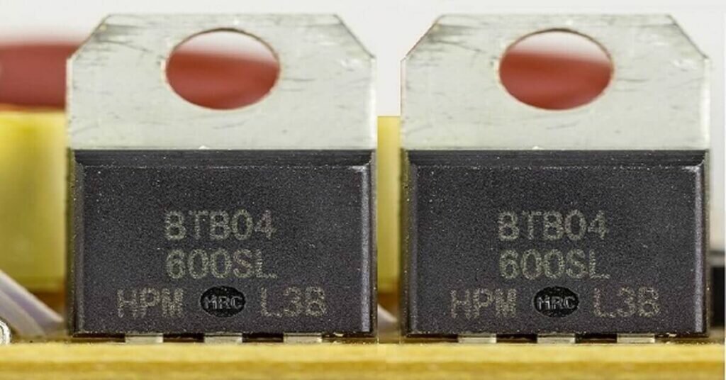
- BT136 (Triac)
- DB3 (diac)
- Resistor 4k
- Variable resistor (0-500k)
- Capacitor 100 nF
Connect all components as the circuit shown below.
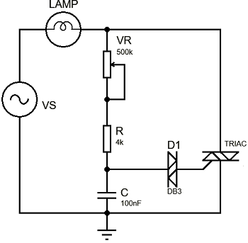
By changing the value of the variable resistor we can change the phase angle and hence power.
Before understanding how this circuit works let’s understand the functions of all components in the circuit. There are already posts uploaded on resistor, capacitor, and triac. Now let’s understand the function of diac.
Diac : introduction
Diac is like a diode for alternating current. It doesn’t have a gate terminal like triac. We turn it “ON” using a high forward voltage. It is mainly used to trigger the gate terminal of triac. It has two terminals: mT1 and mT2.
Diac symbol
Here you can see that it has only two terminals. It turns on with high forward voltage. which we will see in the characteristics graph of diac.
VI characteristics of diac
As you can see that it has almost the same characteristics as the triac. But, since it has no gate terminal so its forward blocking voltage is fixed. From the graph, you can see that if we apply voltage more than or equal to its forward blocking then it will turn on. Once it is turned on, it can be operated in lower voltages as well.
Structure of diac
Its structure is also almost the same as the triac and the difference is the same as always, its gate.
Working of circuit of AC dimmer
Now we will understand how the circuit for the AC dimmer works.
As we give supply to the circuit, during the positive cycle, the capacitor starts charging through resistor R and variable resistor VR. So, the charging time of the capacitor depends on the value of the variable resistor VR. If the value of VR is more then charging time will be more and if its value is less then the charging time will be less. The voltage across the capacitor will be positive. As the voltage across the capacitor reaches the forward blocking voltage of diac, it turns on and triggers the gate of triac and triac will conduct.
Since diac works same also with negative voltages. So, in the negative cycle of AC voltage, the capacitor charges negatively and as it approaches the forward blocking voltage of diac, it turns “ON”. This will trigger the triac and it will start conducting. So, this way we can control the phase angle of the AC signal.
Note: – play carefully with AC mains. Mishandling with it can cause fatal injuries. Always wear globs before touching any wire.
I think this is one of the most vital info for me. And i’m glad
reading your article. But should remark on few general things, The site style is
ideal, the articles is really excellent : D.
Good job, cheers
I have read so many posts about the blogger lovers howeverthis post is really a good piece of writing, keep it up.
whoah this blog is wonderful i really like reading your articles. Keep up the great paintings! You realize, a lot of people are hunting round for this info, you could help them greatly.
I have read so many posts about the blogger lovers howeverthis post is really a good piece of writing, keep it up.
Always so interesting to visit your site.What a great info, thank you for sharing. this will help me so much in my learning