As we know that Arduino is a digital device and doesn’t have the DAC (digital to analog converter). So, basically, it cannot generate a sine wave. But it has some PWM pins by which we take analog output by using the analogWrite function. In this project, we will discuss whether we can generate a sinewave using manipulating the PWM output of the Arduino or not. In this project, we will see only Arduino as a sine wave generator. An upcoming project will be Arduino triangular wave generator.
We know that a signal generator can generate a lot of signals such as sinewave, triangular wave, square wave, etc. This is a very useful and important tool to see the frequency response of audio, op-amp, and other circuits under test. Today’s modern function generator can generate frequencies in megahertz.
I know that Arduino will not perform as well as these modern function generators. But we will do this project to learn and for experiment purposes.
Table of Contents
Components that we need for this project
| Components | Quantity | Amazon links for India | Amazon links for other countries |
|---|---|---|---|
| Arduino UNO board | x1 | ||
| Capacitor (470µF) | x1 | ||
| Oscilloscope (to view the output waveform) | x1 |
If you wish to buy an oscilloscope then I have a detailed guide on buying an oscilloscope.
First, let’s see what a PWM signal is. You can skip this part if you already know about the PWM.
Arduino analogWrite function and PWM signal
Arduino UNO has 6 PWM pins on board. Using these pins we can take the analog output from Arduino. We can dim the brightness of the LED. As mentioned before that PWM is responsible for analog output from Arduino. Let’s see what PWM is?
PWM (pulse width modulation)
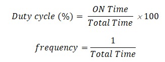
PWM stands for “pulse width modulation”. In PWM we switch rapidly any circuit between 0 volt and high (5 volts in the case of Arduino) voltage. By changing the “ON” and “OFF” time periods, we can get different analog voltages. This time period is called the duty cycle. For example, if “on” time is equal to “off” time then the duty cycle will be 50% and voltage will be 2.5 volts. Let’s understand it graphically.
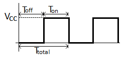
Where:
TON = ON time
TOFF = OFF time
VCC = ON state voltage
TTotal = Total time period
If duty cycle is 50% and VCC is 5 volt then average voltage will be
VAVG = 5 volt×50% = 2.5 volt
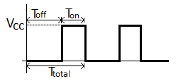
If duty cycle is 25% and VCC is 5 volt then average voltage will be
VAVG = 5 volt×25% = 1.25 volt
In Arduino, we can define the analog output voltage using an 8-bit number from 0 to 255. Where 0 means 0 volt and 255 means 5 volts. That means we have 28 = 256 different voltage levels from 0 to 5 volt to define so the minimum voltage step will be around 20mV. So, we can change the voltage on any PWM pin by a minimum of 20mV. This means that we can define the duty cycle of the PWM signal with a number from 0 to 255, where 0 means 0% and 255 means 100%.
We will average the PWM signal of Arduino using a low pass filter.
Concept behind generating sinewave from Arduino
Sampling theorem
The concept behind creating the sinewave from Arduino is very simple. We will use the digital signal processing (DSP) concept to create a sinewave. First of all, we will take samples of the sine wave at a particular sampling rate. Then we will convert the sampled data into the range of 0-255 corresponding to the voltage level of that sample. Using this process we will create a lookup table of the PWM values corresponding to a sine wave.
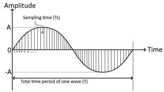
In the figure, sampling of a sine wave is shown. Here Ts is the sampling interval so the sampling frequency will be Fs = 1/Ts. T is the total time period of the sine wave so the frequency of the sine wave will be F = 1/T. According to Nyquist’s sampling theorem,” sampling frequency must be more than twice of the highest frequency component of the signal we are sampling“. That means Fs > 2F.
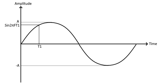
Let’s say we have m number of samples in one time period of the sine signal. So time instance of each sample will be the sample number multiplied with the sampling time (t = n1 to mTs or t = n1 to m/Fs). We will use this data to sample the sine wave using the formula sin2πFt. This function will give us the value of the sine wave at the time instance t.
Convert sampled data to 0-255 PWM range
In the Arduino programming language, there is a “sin” function available. This sin function takes the angle value in radians and gives the sine value of that angle from -1 to 1. We can use that function to create the lookup table of PWM values. But the output of the function ranges from -1 to 1, so we have to multiply it by 255 to find the correspondence PWM value. But that way we will also get the negative value of PWM and Arduino accepts only positive PWM value to output analog voltage.
So we have to shift the sin output by 1 to make the range from 0 to 2. That means we have to add 1 to the output of the sin value. Then we will multiply this value from 127. This way if the sin value is 0 then we will get 0 PWM value and if the sin value is 2 then will get 254 PWM value. That will make a 0-5v output at the Arduino’s PWM pin according to the sine signal.
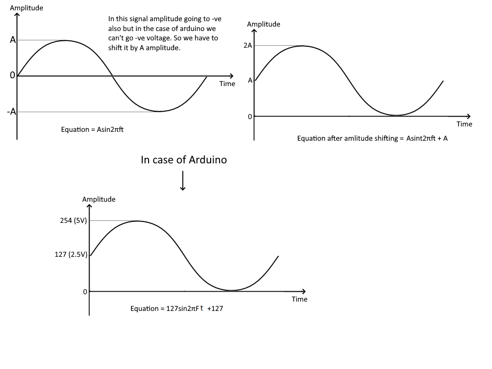
So we have obtained the equation as 127sin2πFt.
Minimizing the sampling formula
Since we are sampling only the value of the sine signal at different time instances. The frequency of the reconstructed signal will be defined as how much time interval we have taken to plot the samples. For example, we are taking 500 samples of a 1Hz sine signal for one complete cycle so the sampling frequency is 500Hz and the sampling interval will be 2mS. Now If we plot all 500 samples only in 0.5 seconds with a sampling interval of 1mS then the output frequency will be 2Hz.
We will do the same here. We will sample a 1Hz sinewave for one period and store it in an array. Then we will output each sample with a different time interval to get different frequency signals.
To sample 1Hz signal we will use this formula – sin2πt
The Arduino code
int F = 2;                                                   //frequency of the signal
int Fs = 500;                                                //sampling frequency
int n = 500;                                                 //number of samples
float t;                                                     //Time instance
int sampling_interval;
byte samples[500];                                           // to store the samples

void setup() {

  pinMode(10, OUTPUT);
  for (int n = 0; n < 500; n++)
  {
    t = (float) n / Fs;                                       //creating time isntance to find the 500 samples
    samples[n] = (byte) (127.0 * sin(2 * 3.14 * t) + 127.0 ); //calculating the sin value at each time instance
  }
  sampling_interval = 1000000 / (F * n);
  //sampling interval Ts = 1/frequency x number of sample (Ts = 1/Fn or Ts = T/n)x1000000 to convert it in µS
}

void loop() {
  for (int j = 0; j < 500; j++) {
    analogWrite(10, samples[j]);
    delayMicroseconds(sampling_interval);                      //time interval
  }
}
This is the code to use Arduino as a sine wave generator. We have taken variables to store the frequency of the signal, sampling frequency, number of samples, time interval, and samples of the sine signal. In the void setup, we have declared pin 10 as output and we have implemented the formula to find the samples of the sine wave. For finding the 500 samples we have repeated the calculation 500 times with different time instances with the help of a for a loop. Then we have calculated the time interval in microseconds according to our desired frequency output. Then in the void loop function, we have plotted the samples with the time interval we have calculated.
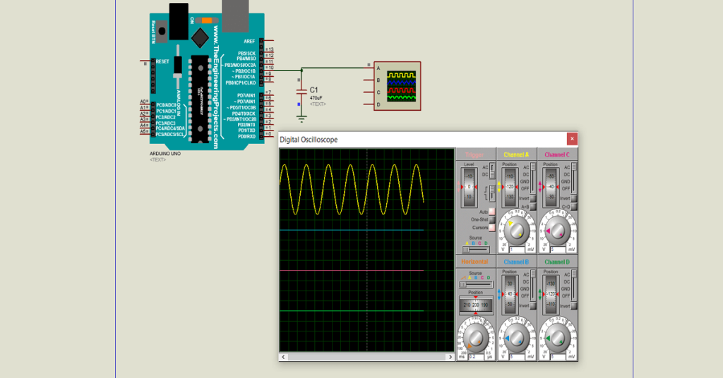
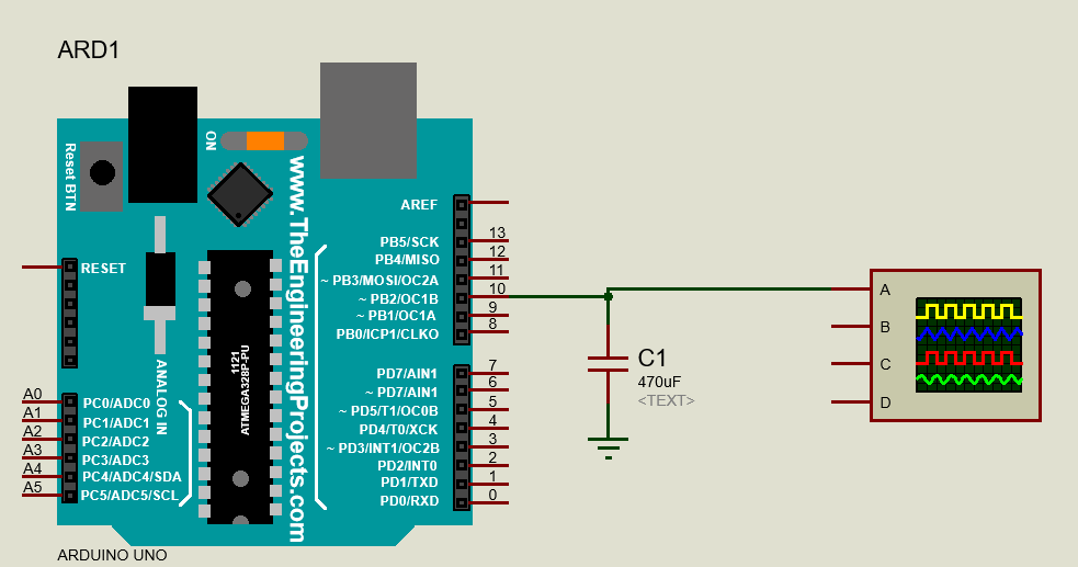
Circuit of Arduino sine wave generator
Here is the circuit of the Arduino sine wave generator.
Output Of Arduino sine wave generator
Now let’s see the output on the Oscilloscope.
This is the perfect webpage for everyone who wishes to understand this topic. You realize so much its almost hard to argue with you (not that I personally would want toÖHaHa). You definitely put a brand new spin on a subject that has been written about for a long time. Great stuff, just great!
I tried increasing the frequency, but past 100Hz it does not yield expected results.
How can I solve this?
It won’t give you the expected result if you go above 50HZ. If you really need to go beyond 50Hz then you need to play around with the sample rate and the timing.
I tought PWM signal before capacitor will have constant magnitude with different width. Please help me.
You are right. PWM has constant magnitude with different width.
Great content. Thanks.
Just trying to figure out why you don’t allow the snippet code to be copied (ctrl c + v).
Selected text don’t highlight but you can copy the text. I’m trying to fix this problem.