The transformer is a very useful electrical device mostly used in transmission lines to change voltage levels. It consists of two electrically isolated coil (inductor) windings.
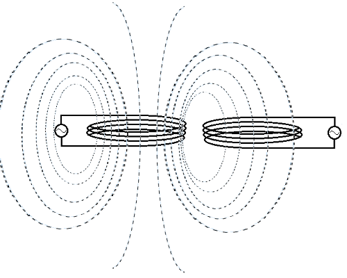
It is electrically isolated but transfers energy using a changing magnetic field. The working principle of a transformer is mutual induction between both (it can be more than two) winding. Mutual induction happens only with an alternating (changing) magnetic field. This is the reason that transformer works only with AC. When we pass AC current through a coil it generates an alternating magnetic flux. If another coil is brought close to this coil then some of that magnetic flux link with this coil and generate an alternating voltage across the coil. This is called mutual induction.
As said earlier, a transformer is used widely in transmission lines where we use alternating current and voltages. Because AC voltages are easily generated and transformed into much higher voltages that reduce the current flowing through the transmission line. Less current lowers the waste of power (i2*R). So, power can be distributed over long distances. After distributing this high voltage is again transformed to a lower voltage for supply electrical equipment. So, basically, a transformer is used to transform AC voltages. This is why we call it a transformer. There are not any moving parts in a transformer. This is an electro-magnetic passive electrical device. This works on the principle of Faraday’s law of induction.
You must have understood by now that a transformer is capable of either increasing the voltage or decreasing it. The transformer doesn’t change the frequency of AC current or Voltage or power given to it. A transformer that boosts (increases) the voltage is called a “step-up transformer” and a transformer that decreases the voltage is called a “step down transformer”.
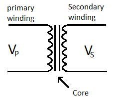
As we know transformer consists of two winding. One of its winding is called “primary winding” and the other is called “secondary winding”. The winding at which we give the power is called primary and from the winding, we take the power is called secondary winding. This winding is wrapped around an “iron core”. This iron core is made up of individual laminated plates of iron to avoid losses on the core due to eddy current
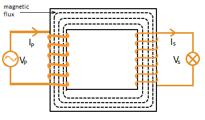
Here:
IP is the primary current
IS is the secondary current
Magnetic flux is Φ
As you can see in the figure above, there is no electrical connection between primary and secondary. They are isolated from each other. The winding to which AC source VP is connected is primary winding and winding to which bulb is connected is the secondary winding. The job of the primary winding is to take the power from a source and convert it into an alternating magnetic field. Secondary winding then converts that alternating magnetic field into electrical energy.
A step-up transformer has more number of turns wire on the secondary than the primary winding and unlike a step-down transformer which has fewer turns on the secondary than the primary. The ratio of the primary and secondary winding is called “turn ratio (TR)”. The third type of transformer which is called “impedance transformer” whose turn ratio is 1:1 is also exists. It is used to connect two circuits with different impedances.
The difference between primary and secondary voltage depends upon the turn ratio. It has no unit, it just compares the windings. If the turn ratio is 1:10, this means if there is one volt across primary winding there will be 10 volts on the secondary. Hence this is a step-up transformer.
In an ideal transformer (where ΦP (magnetic flux through primary winding) = (magnetic flux through secondary winding)-
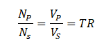
Where:
VP is the primary voltage
VS is the secondary voltage
NP is the number of turns on the primary winding
NS is the number of turns on the secondary winding
According to this equation “turn ratio = voltage ratio”. That means if we increase or decrease the number of turns on secondary or primary winding we can change the voltage ratio. In fact, transformers are defined in turn ratio.
Table of Contents
Transformer construction and symbol
A transformer is two winding of wire on an iron core. The iron is not a completely solid metal rather it is sliced into iron plates and all plates are laminated to avoid power loss due to Eddy current.
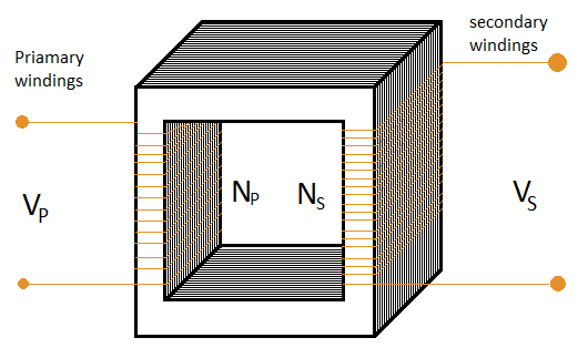
Here:
VP is the primary voltage
VS is the secondary voltage
NP is the number of turns on the primary winding
NS is the number of turns on the secondary winding
Transformer’s working fully explained
We know that both windings of the transformer are isolated. Energy is transferred by a magnetic field. But how does the magnetic field transfers energy? Let us explain.
Faraday’s Law of electromagnetic induction states that “magnetic field is getting stronger with rising current from zero to maximum. The change in current creates changing magnetic flux given as dΦ/dt.
When we connect the transformer’s primary winding to an AC source, which is sinusoidal and its equation is ![]() . So, current will be also sinusoidal in nature. Due to this magnetic flux developed around primary will also be sinusoidal.
. So, current will be also sinusoidal in nature. Due to this magnetic flux developed around primary will also be sinusoidal.
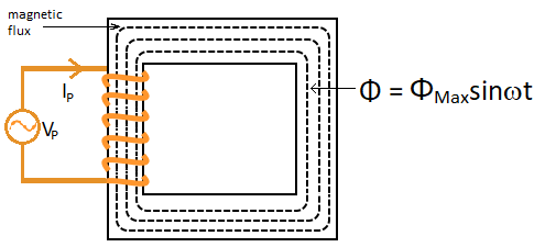
As the iron core is more magnetic than air so, it will choose its path through the iron core. Since the secondary coil is also wound on this so the magnetic flux will link to the secondary winding. When the magnetic flux passes through the iron core it also passes through the secondary winding. That causes an induced voltage into secondary winding.
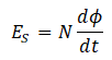
Where:
ES – induced EMF across the secondary winding
N – Number of turns in the secondary winding
dΦ/dt – Change in magnetic flux
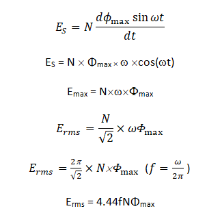
Where:
N – Number of turns of coil winding
Φmax – the maximum amount of flux
f- is the frequency
This is the transformer EMF equation.
Note that the transformer needs alternating magnetic flux to work properly. Therefore, the transformer cannot operate on DC because it offers a steady current. Which cannot develop an alternating magnetic flux. If you want mathematical proof then see the above equation. It needs an oscillating power source that has a frequency. But, DC has zero frequency. Rather if we connect a DC power source to primary winding it will short the source and a huge current will flow.
Power in a transformer
An important transformer parameter is its power. We know that power is the multiplication of voltage and current. So, the power rating of a transformer is measured in Volt-ampere (VA).
Some bit big units of power are:
Kilo volt-ampere (kVA)= 1000 volt-ampere (1000 watts)
Mega volt-ampere (MVA) = 106 volt-ampere ( 1 million watts)
An ideal transformer delivers the same amount of power that we gave to it but, in practice, there are some losses in the transformer like hysteresis loss, eddy current, etc. So, practically PS<PP.
How much power we applied on primary and how many portions of that power we get on secondary depends on the transformer’s efficiency.
Efficiency and losses in a transformer
As mentioned earlier that there are some losses in transformers. Some losses are associated with a wire that is wound on an iron core to make winding and some are associated with the iron core itself.
Power loss in the wire is due to its resistance. Every wire has some resistance and when the current passes through it, it causes some loss of power.
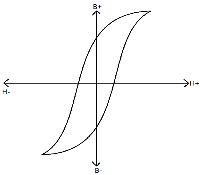
A loss associated with the iron core is hysteresis loss. This loss occurs due to the magnetic property of iron. If we put iron in a magnetic field and start increasing the magnetic field, a moment will come when we increase the magnetic field further the magnetization of iron will not increase. After reaching that condition we need some power to take iron back to its previous condition. In this process, some power loses, and the current starts lagging from voltage.
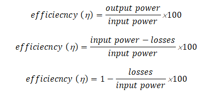
Using this formula we can calculate the efficiency of any electrical/electronic device.
Applications
The main application of a transformer is to step up or step down the voltages.
- In transmission line
- In power supplies
- For electrically isolate two circuits
- To match the impedances of two circuits
Hi! I simply would like to offer you a big thumbs up for the excellent
information you have here on this post. I will be returning to your web site for more soon.
This design is incredible! You most certainly know how to keep a reader entertained.
Between your wit and your videos, I was almost moved to start my own blog (well, almost…HaHa!) Great job.
I really enjoyed what you had to say, and more than that, how you presented it.
Too cool!
Thank you for some other excellent article.
The place else could anybody get that type of info in such an ideal approach of writing?
I’ve a presentation next week, and I am at the
look for such info.
Heya are using WordPress for your blog platform? I’m new to the blog world but I’m trying to get started and create my own. Do you need any html coding knowledge to make your own blog?
Any help would be really appreciated!
No, you don’t need any coding to start a blog with the wordpress.
I like the helpful info you provide in your articles. I?ll bookmark your weblog and check again here frequently. I’m quite certain I?ll learn plenty of new stuff right here! Best of luck for the next!
Hiya very nice web site!! Man .. Excellent .. Superb .. I will bookmark your site and take the feeds additionally?I am happy to seek out a lot of helpful info right here within the put up, we need work out extra strategies in this regard, thanks for sharing. . . . . .